
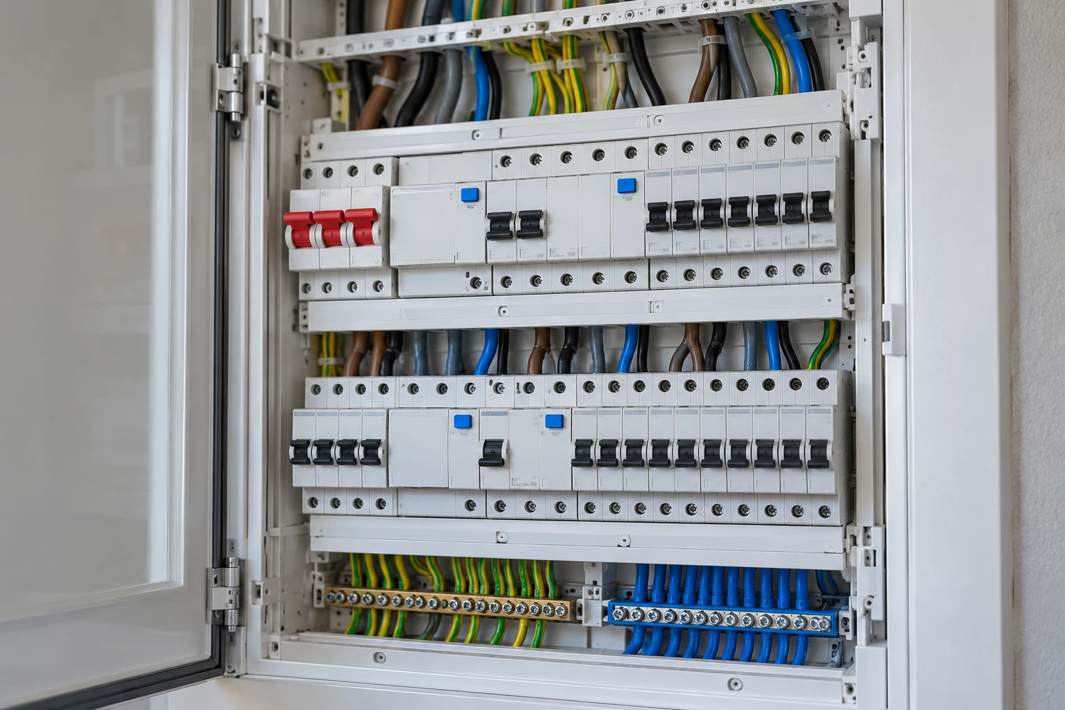
MechScript · in-depth technical guide · October 2026 · part of the Energy & Electricity series
For whom: technically interested readers, homeowners, Home Assistant users and professionals who want to understand a home distribution board better.
Safety: this article explains operating principles, not wiring diagrams to install from. Electrical equipment inside a distribution board may carry 230/400 V and deliver very high fault currents. Have qualified personnel perform work on live parts.
Why this follow-up?
Our basic article about the distribution board discusses the assembly as a whole. This follow-up focuses on the components, their markings and the mechanisms inside individual switches and protective devices.
1. Reading guide: look without danger
A distribution board is an assembly of separate components. You recognize them by function, markings and position in the system. This article goes a step further than an overview: we examine the technology behind each part.
What you can do as a resident
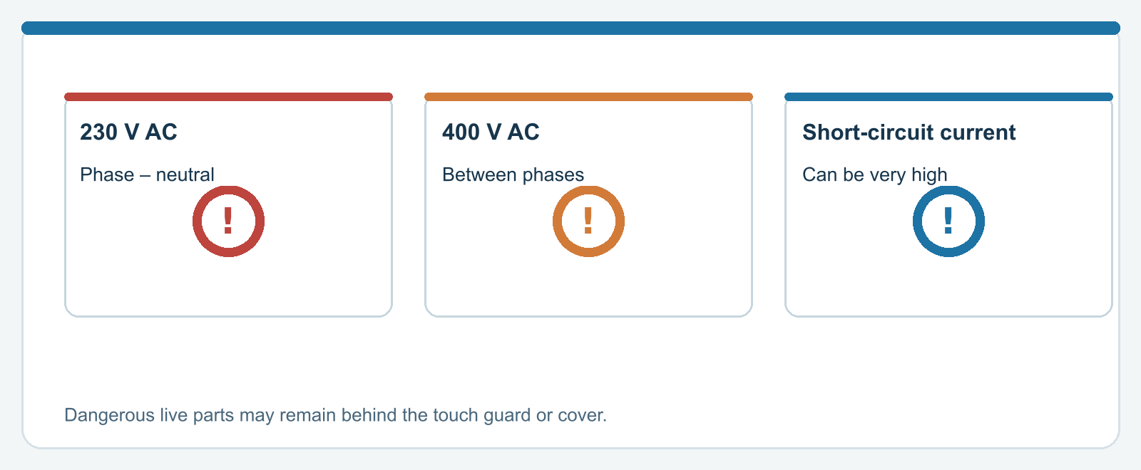
You can identify the controls on the outside, check your circuit labels and use an RCD's test button according to its instructions. Operate an accessible switch only when conditions are safe.
What you should not infer from this article
The pictures are functional cross-sections and illustrations. They are not usable wiring diagrams. Connection direction, neutral arrangement, busbar choice, enclosure design and protective concept depend on the brand, supply and installation.
The actual hazards
An open board can contain 230/400 V even after one part has been switched off. A fault can produce very high short-circuit currents. Solar panels, UPS systems and home batteries can also create multiple power sources.
Warning: Safe boundary: opening, connecting, modifying and measuring live parts are jobs for qualified personnel. A main switch does not guarantee that every source is de-energized.
2. Components at a glance
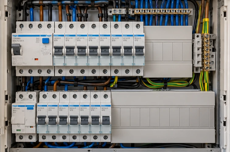
Most modern residential boards have a recognizable core: a main switch, protection against earth faults and overcurrent, and busbars distributing power. The exact arrangement depends on the design.
Switching
The main switch isolates the installation from its normal supply. A contactor can switch a load remotely, but does not replace suitable protection.
Protection
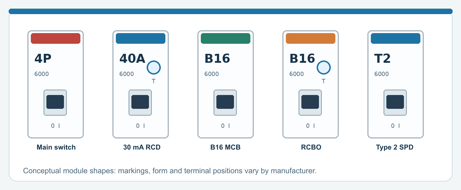
A residual-current circuit breaker (RCCB) monitors the difference between outgoing and returning current. A miniature circuit breaker (MCB) interrupts overloads or short circuits. A residual-current circuit breaker with overcurrent protection (RCBO) combines both.
Connecting and measuring
A comb busbar distributes power to compatible modules. Neutral and protective-earth facilities serve different purposes. Energy meters provide information but do not change protective functions.
Warning: Not every white DIN-rail module is a protective device. Its symbol and type designation determine what it actually does.
3. The main switch is not a fuse
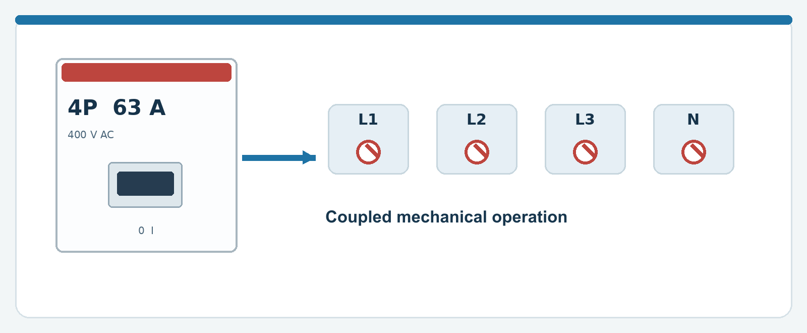
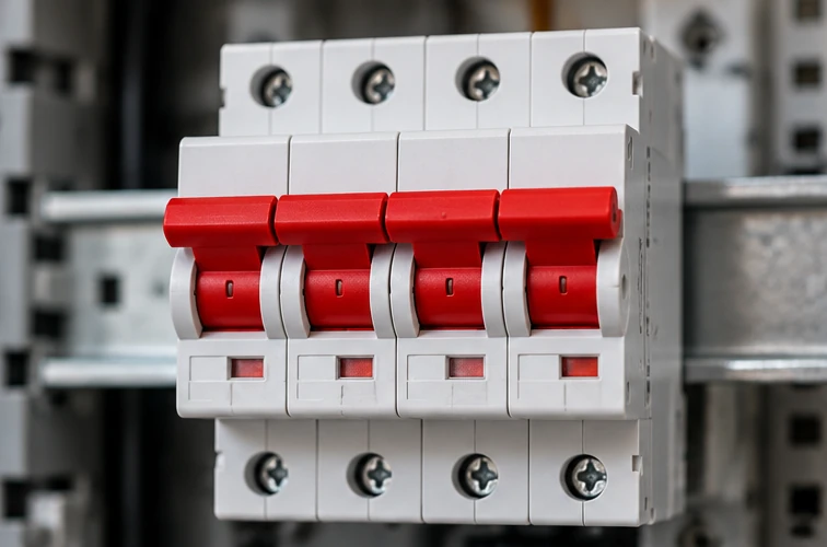
The main switch is the central manually operated isolator for the normal grid supply. In a three-phase installation, it is usually a four-pole device. It is neither an MCB nor an RCD.
What happens inside?
Mechanically linked contacts interrupt the relevant live conductors together. Switching capacity and suitability for isolation are stated on the rating label or in the datasheet.
What does 40 A or 63 A mean?
This is the switch's rated current under specified conditions. It does not mean the switch automatically trips at 40 or 63 amperes. Protection against excessive current comes from elsewhere in the installation.
Four poles are not merely four separate switches
The mechanism is linked so the phases and the designated neutral switch together. Whether the neutral should be switched follows from the applied system and design.
Warning: With PV or battery storage, voltage can arrive from another direction. Never rely on the position of one lever when dealing with unknown wiring.
4. How the RCD detects a fault
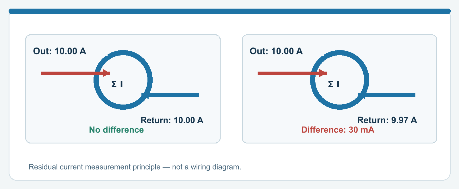
An RCD compares current entering the protected part through the live conductors with the current returning. In normal operation, the vector sum is almost zero.
The sensing core
Phase and neutral pass through a common sensing core. Normally their magnetic effects cancel. A difference produces a signal that can activate the trip mechanism.
An example with 30 mA
If 10.00 A flows to an appliance and 9.97 A returns through the intended conductors, 0.03 A is missing: a residual current of 30 mA. A suitable 30 mA RCD is designed to trip when the fault current is sufficiently large.
Not the same as an MCB
A plain RCCB does not measure overload or short-circuit current. The design therefore needs separate current and short-circuit protection.
Warning: 30 mA is the rated residual operating current (IΔn). It is no promise that 29 mA is always safe or that every electrical accident will be prevented.
5. Reading an RCD's markings
An RCD carries several values that are easily confused. Together they tell you about maximum operating current, sensitivity, fault-current type and construction.
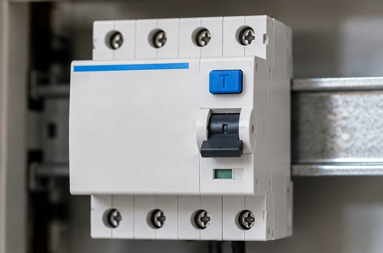
40 A is not the trip current
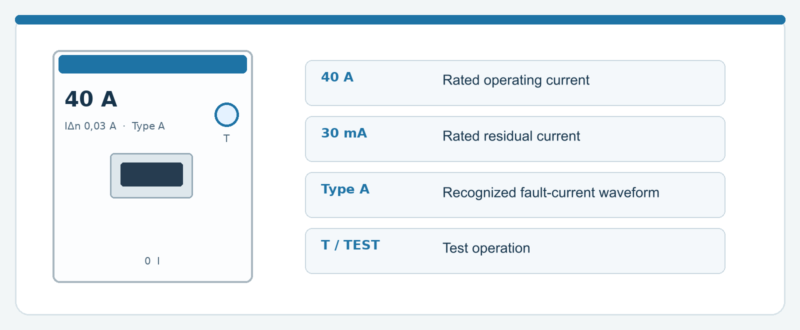
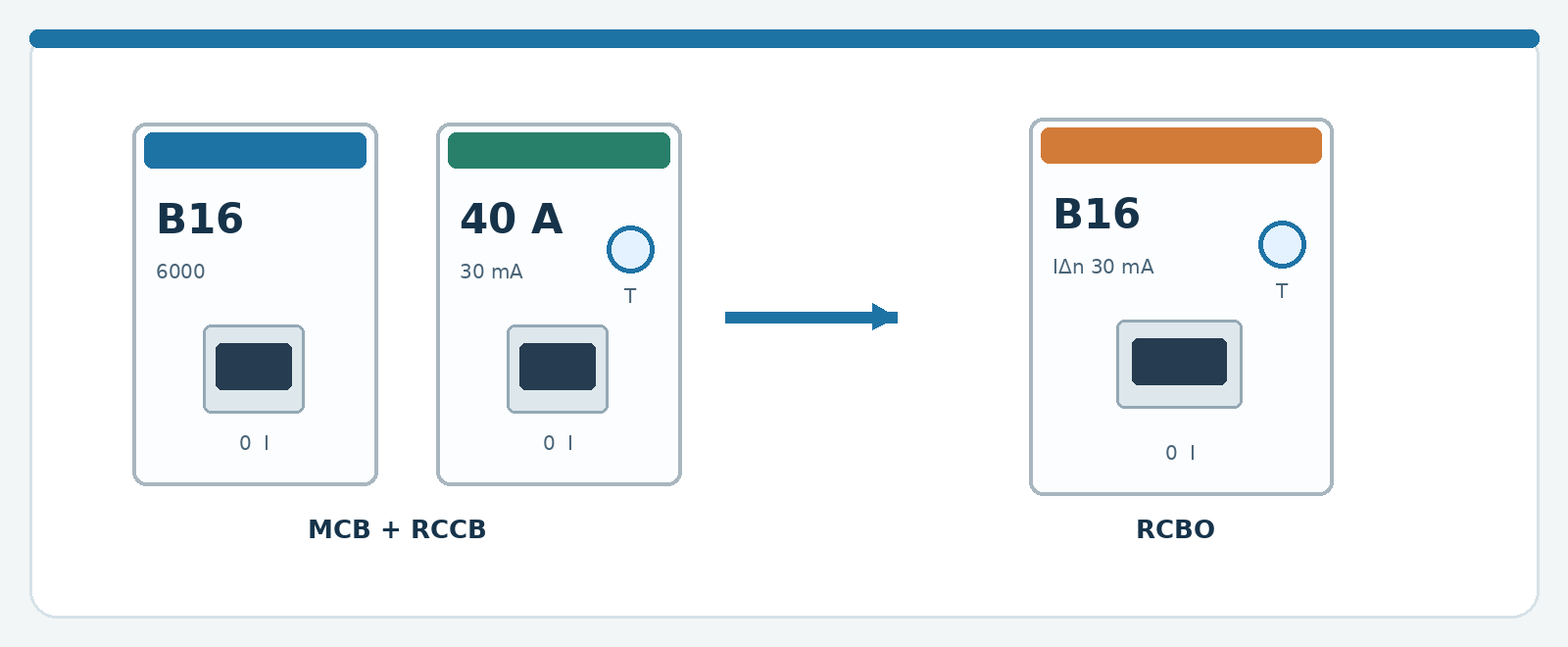
On an RCCB, 40 A usually means the rated current for which it was designed. During an overload of, for example, 45 A, this RCD need not trip by itself.
IΔn 0.03 A = 30 mA
This value concerns residual current, not the ordinary current consumption of connected equipment. In residential installations, 30 mA is a common value for additional protection of people.
Type A, test button and four poles
Type A indicates the fault-current waveforms the device can detect. The T or TEST button tests a mechanism through an internal test circuit; it does not replace an instrumented test. A 4P device has four linked current paths.
Warning: A test button that does not cause a trip, or a switch that trips again immediately, is a reason to have the installation investigated.
6. Types A, F and B: what changes?
The type of residual-current protection describes the forms of residual current it can recognize. Modern electronics can produce not only sinusoidal AC residual currents but also pulsating DC and mixed-frequency components.
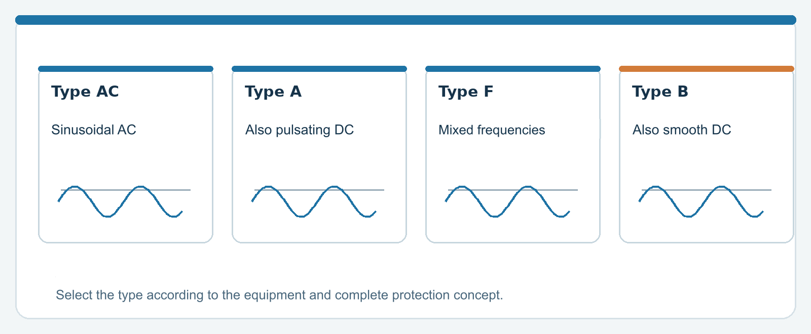
Type AC and type A
Type AC responds to sinusoidal AC residual current. Type A also detects pulsating rectified residual current. For many modern household applications, type A is the usual starting point.
Type F
Type F is designed for additional characteristics of certain single-phase variable-frequency loads, including certain mixed frequencies. It is not a universal replacement for type B.
Type B and EV charging
Type B can also detect smooth DC residual current. For EV charging, type A with suitable 6 mA DC detection in the charger may sometimes suffice; the requirements depend on the charger and protective concept.
Warning: Choose the right RCD type from the documentation of connected equipment and the installation design. “Type B is always better” is too broad a conclusion.
7. Inside the MCB
An MCB protects a conductor from unacceptable overcurrent. A common thermal-magnetic type uses two separate trip mechanisms and an arc-extinguishing arrangement.
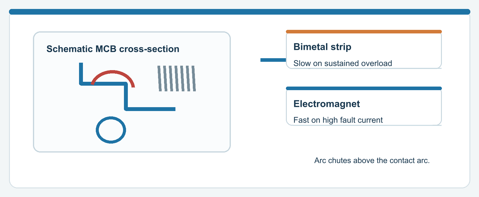
Thermal: the delayed response
With a moderate overload, a bimetal heats up, bends and releases the trip mechanism. The greater and longer-lasting the overcurrent, the faster that happens. At a normally permitted load, the device remains on.
Magnetic: the fast response
A strong short-circuit current activates an electromagnetic mechanism. It can open the contacts very quickly. The resulting switching arc must then be extinguished safely.
The arc chamber
Several metal plates divide and cool the arc. An MCB is therefore not simply a switch with a spring: safely interrupting fault current is a central design task.
Warning: A fault may be serious even if an MCB trips. Repeatedly turning it back on is not a way to find the cause.
8. B16, C16, 6 kA: read the label
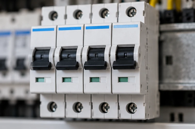
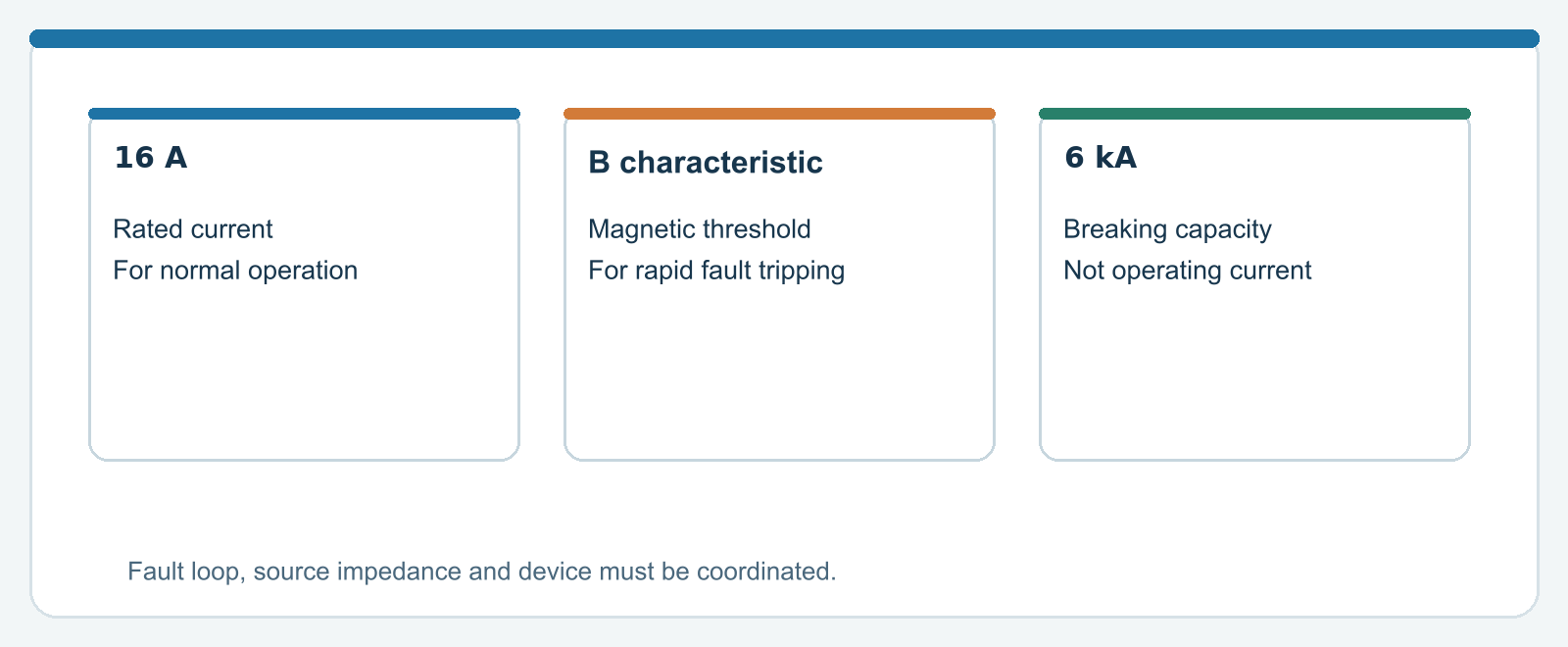
“B16” contains two separate facts: B is a trip characteristic and 16 is the rated current in amperes. The label also gives breaking capacity and the product standard.
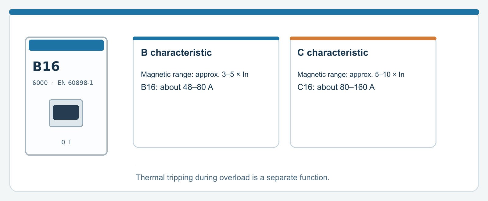
B versus C
For common MCBs under EN 60898-1, the instantaneous magnetic trip range is roughly 3–5 × In for B and 5–10 × In for C. Thermal action during prolonged overload does not disappear.
What does 6 kA mean?
6 kA is the rated short-circuit breaking capacity under the relevant product standard. It is not the operating current, does not suggest that thousands of amperes normally flow and does not guarantee suitability in every installation.
The cable must be suitable
Selecting C16 instead of B16 to avoid nuisance tripping can be dangerous if fault-loop impedance and disconnection time do not match. An installer assesses the breaker, cable, source and fault current as a whole.
Warning: A 16 A breaker is not a hard power limiter that opens instantly at exactly 3,680 W. Both time and current determine when it trips.
9. The RCBO: two functions
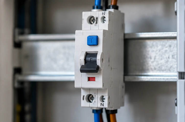
An RCBO combines the functions of a miniature circuit breaker (MCB) and a residual current circuit breaker (RCCB). It can therefore respond to overcurrent as well as a residual current fault.
Why are they increasingly common?
An RCBO can provide an individual final circuit with its own residual current protection. An earth fault on that circuit may then affect fewer other circuits than when many final circuits share one RCCB.
B16 and 30 mA appear on one device
B16 describes overcurrent protection. The 30 mA marking describes residual current protection. These address two different hazards within one housing.
1P+N does not automatically mean double overcurrent protection
A 1P+N version may disconnect the neutral without independently protecting it against overcurrent. The number of poles and internal arrangement are shown by the technical symbol and data sheet.
Warning: Not every RCBO fits every busbar or enclosure range. A mechanical fit does not establish system compatibility.
10. Busbars: distributing the supply
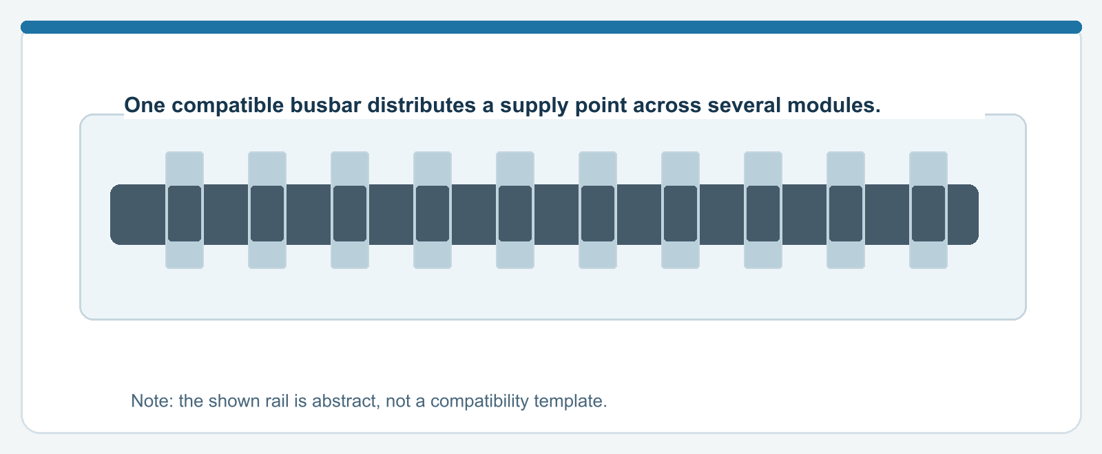
A comb busbar or supply busbar distributes voltage to modules designed for it. This can be compact, clear and provide predictable contact quality, provided the components belong together.
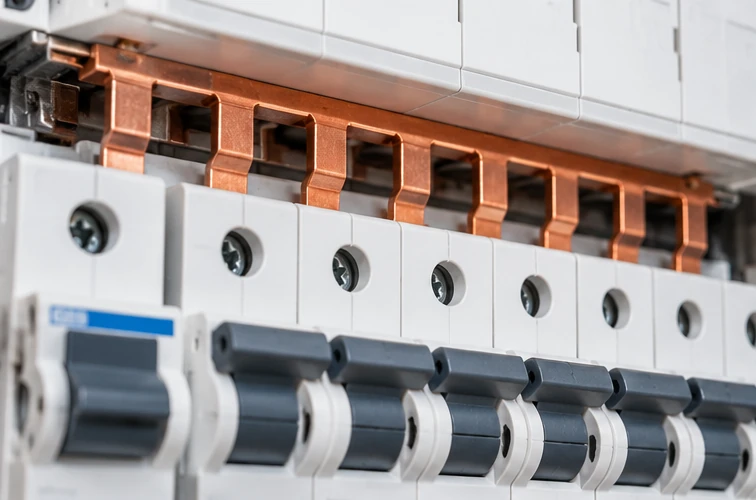
Pin or fork busbar
Manufacturers and modules use different pin or fork contacts. Profile, insulation, rated current, feed arrangement and shielding vary. A busbar is therefore not a universal hardware-store accessory.
The rail is also a thermal component
With heavy loads, multiple sources or PV feed-in, current distribution across the whole rail system matters. A rating on a single module does not prove that every part of the complete distribution rail is suitable.
Finishing and shielding
Open ends, missing end caps or incorrect clamping can expose live parts. The correct combinations are specified in the distribution assembly’s system documentation.
Warning: Adding modules to an existing busbar without checking compatibility and load can produce an unsafe assembly.
11. Neutral and protective earth bars: do not confuse them
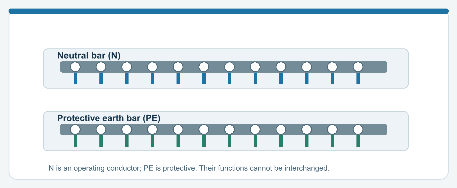
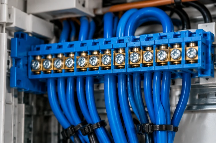
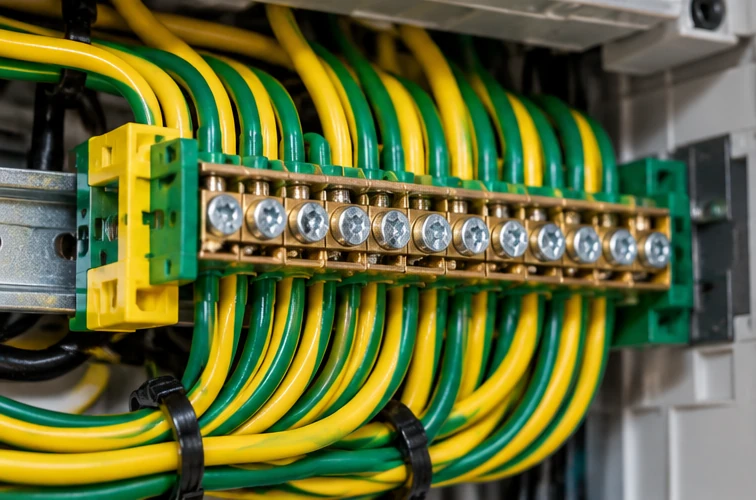
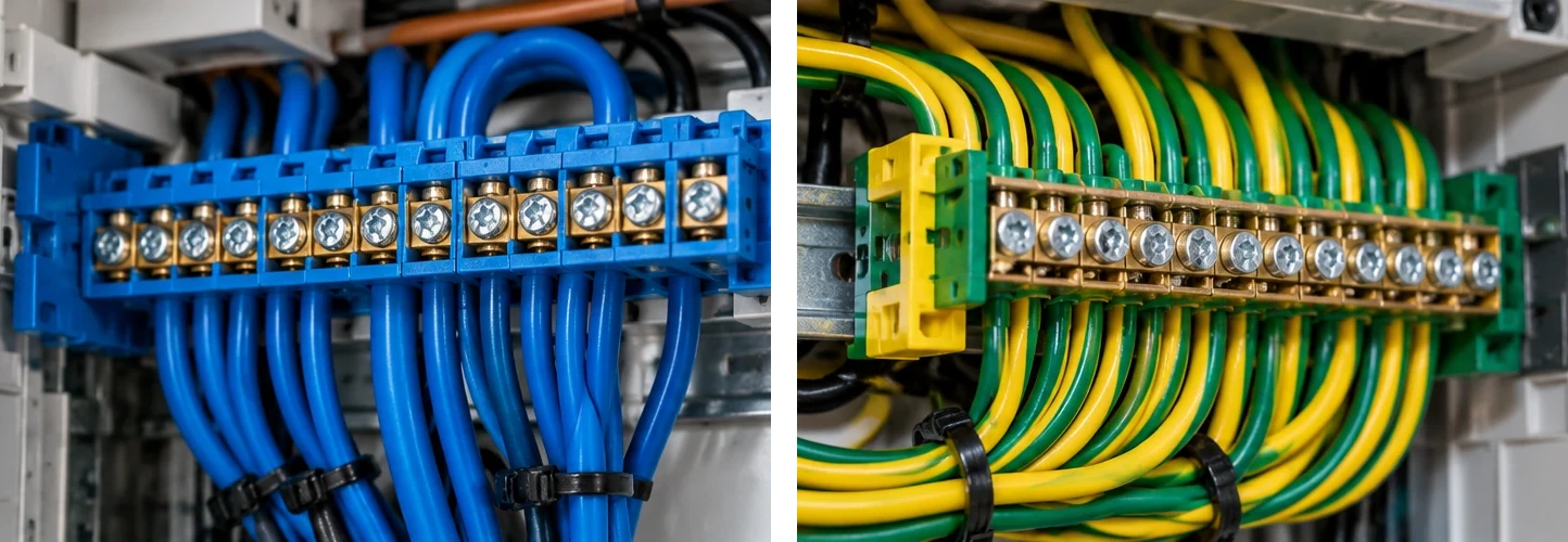
Blue and green/yellow conductors have completely different functions in a distribution board. Neutral (N) is an active operating conductor. Protective earth (PE) is intended for fault protection and bonding.
Why neutral matters
In a single-phase load, the return current normally flows through neutral. A loose or incorrectly connected neutral can cause unstable voltage and outages. In some three-phase situations, a broken neutral can cause very dangerous voltage shifts.
Why earth works differently
PE should not normally carry operating current. It connects exposed metal parts to the protective arrangement so a fault can be handled safely in the applicable earthing system.
Neutrals from different RCD groups
Neutrals from different RCCB/RCBO circuits must not be mixed arbitrarily downstream of their measuring cores. Otherwise the RCD detects an apparent difference and may trip unexpectedly.
Warning: Adding a bridge between N and PE wherever it seems to “make things work” is dangerous. The earthing arrangement and separation point must be correct.
12. L1, L2 and L3: phase distribution
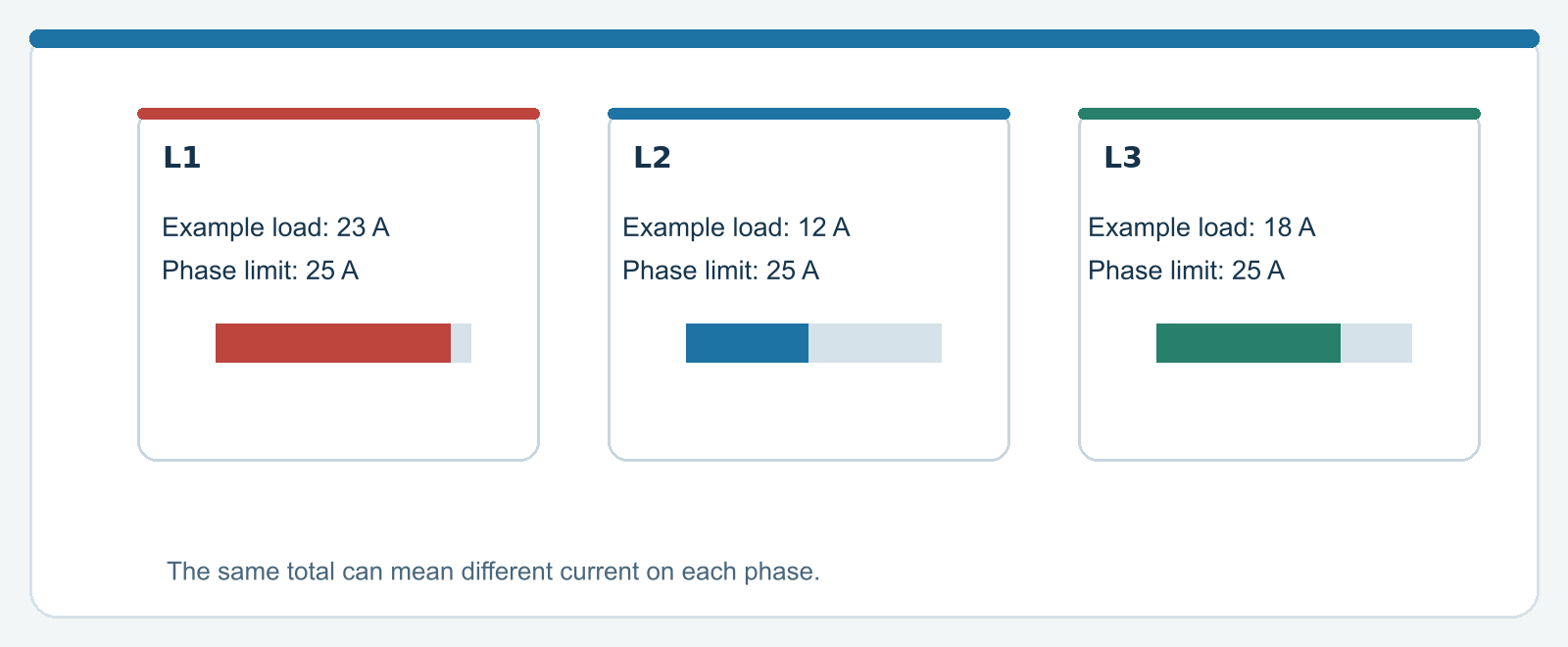
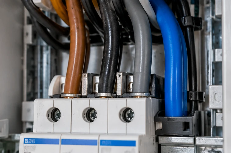
In a three-phase home, the phases are not automatically a single shared pool of current. A 3×25 A connection has a separate current limit per phase. A heavy load on L1 can overload L1 while L2 and L3 still have capacity.
A 3×25 A example
At 230 V, 25 A per phase corresponds mathematically to 5.75 kVA. With three evenly loaded phases, the total is about 17.25 kVA. This is apparent power; real power also depends on the load.
Balance and simultaneous demand
A hob, EV charger, heat pump and boiler can draw substantial power at the same time. The installer therefore considers phase distribution, inrush currents, protection selection and actual simultaneous demand.
What solar panels change
PV can feed energy into another point in the board. Currents in parts of the busbar system then depend on both consumption and generation, rather than the main fuse alone.
Warning: The sum of the three phase powers says nothing about an individual phase that has already exceeded its limit.
13. Poor contacts: small resistance, considerable heat
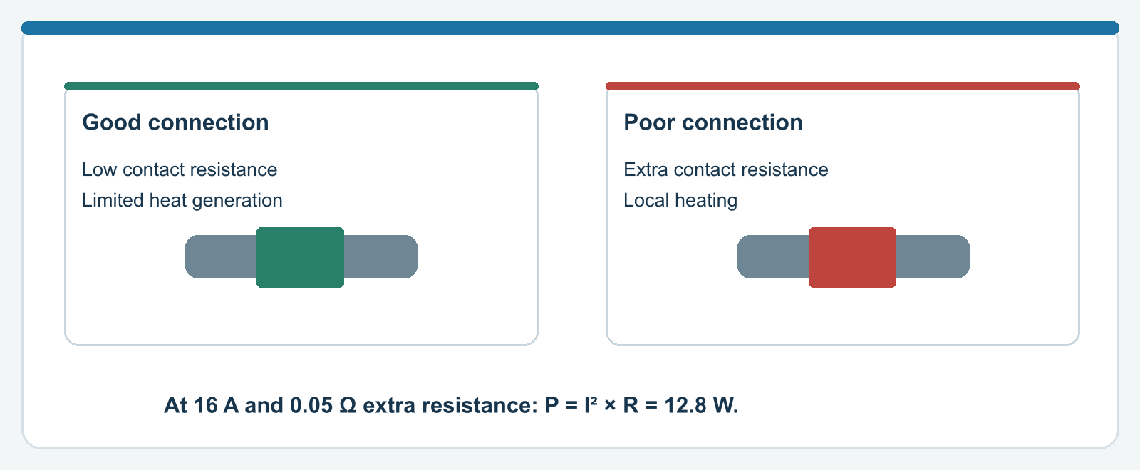
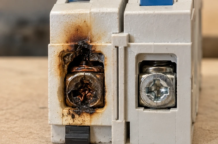
An electrical connection should have very low contact resistance. Even a small added resistance can become quite hot during sustained high current. This is an important fire risk.
Why contact pressure matters
Terminal type, conductor construction, ferrules where required, and the manufacturer's specified tightening torque determine the connection. Loose or otherwise incorrect assembly can cause problems; tightening arbitrarily harder is no solution.
A concrete example
At 16 A and an unwanted contact resistance of 0.05 Ω, P = I²R = 16² × 0.05 = 12.8 W of heat is produced in a very small area. That is enough to heat a connection severely.
Temperature is not uniform
Heat may originate in a terminal, a busbar contact or a defective device. The exterior may look normal. Thermographic inspection requires interpretation of load, emissivity and conditions.
Warning: A burning smell, discoloration, melted plastic or audible crackling means stop using the installation and have it assessed safely.
14. Why does the RCD sometimes trip?
An RCD does not trip only when someone touches a live part. Moisture, defective insulation, electronic filters or an installation fault can also be responsible.
Small leakage currents add up
Many electronic devices have EMC filters that can create a small leakage current. Together these can reduce the available margin. An installer measures residual currents and identifies the correct distribution or underlying cause.
A fault is not always permanent
Moisture in an outdoor socket can cause intermittent behavior. Appliances with heating elements may also develop earth faults only after warming up. Timing or a pattern aids diagnosis but is not proof.
What can a resident do?
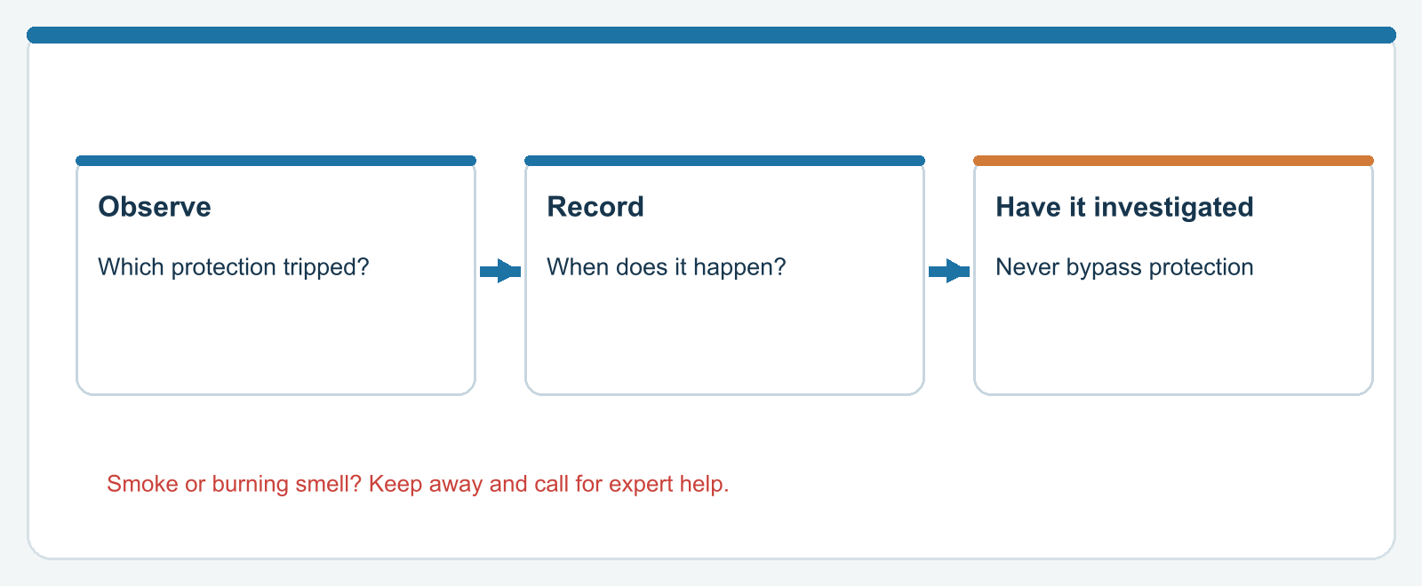
Record which protective device tripped and under what circumstances. If the handle is normally accessible and there are no signs of danger, follow the operating instructions. If the fault recurs, stop self-diagnosis and call a professional.
Warning: Never bypass residual current protection or disconnect a protective earth conductor to “solve” tripping.
15. Selectivity: which device trips first?
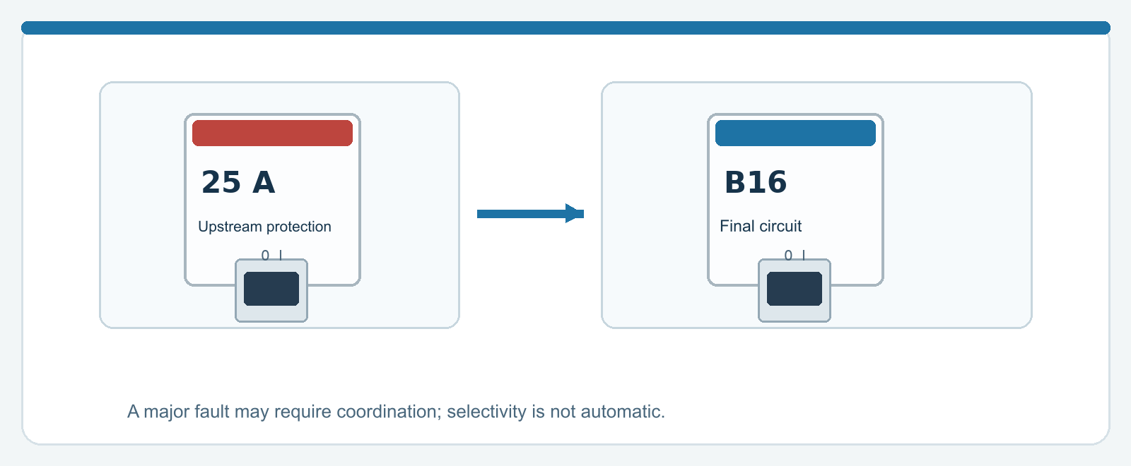
A sound distribution board should handle faults as locally as possible. Selectivity means that, ideally, the nearest suitable protective device trips while the rest of the installation remains available.
Short-circuit currents are not simple numbers
With two circuit breakers in series, it is not always obvious which opens first. Trip curves may overlap, especially at high fault currents. A B16 downstream of a 25 A main protective device is not automatically fully selective in every situation.
Coordinating residual current devices
Two residual current devices in series may require suitable sensitivities and time delays. A selective S-type device is not the same as a standard 30 mA RCD.
Why residents notice this
With poor selectivity, a fault on one final circuit may shut down a larger part of the home. Where appropriate, modern boards therefore often use a separate RCBO for each final circuit.
Warning: Selectivity is substantiated with manufacturer characteristics and coordination tables, not merely the B16 or C16 marking.
16. 6 kA, fault loop and disconnection time
When a phase unintentionally touches another active conductor or a fault path, protection must interrupt the fault before hazardous effects arise. The source, cables, fault loop and device must be considered together.
What is the prospective fault current?
Fault current at a given point follows from mains voltage and the total impedance of the fault loop. It can be higher near the supply than at the end of a long cable.
Why a breaker says 6 kA
The figure describes a short-circuit interruption property of the product. Whether it is adequate depends on prospective short-circuit current, any upstream protection and the applicable coordination.
Time can matter as much as magnitude
Fault protection concerns not only whether a breaker eventually trips, but also how quickly. Measurements and calculations such as fault-loop impedance and RCD tests, where applicable, are part of professional verification.
Warning: Creating a deliberate short circuit with a multimeter to “test” a breaker is extremely dangerous.
17. Surge protection: the SPD
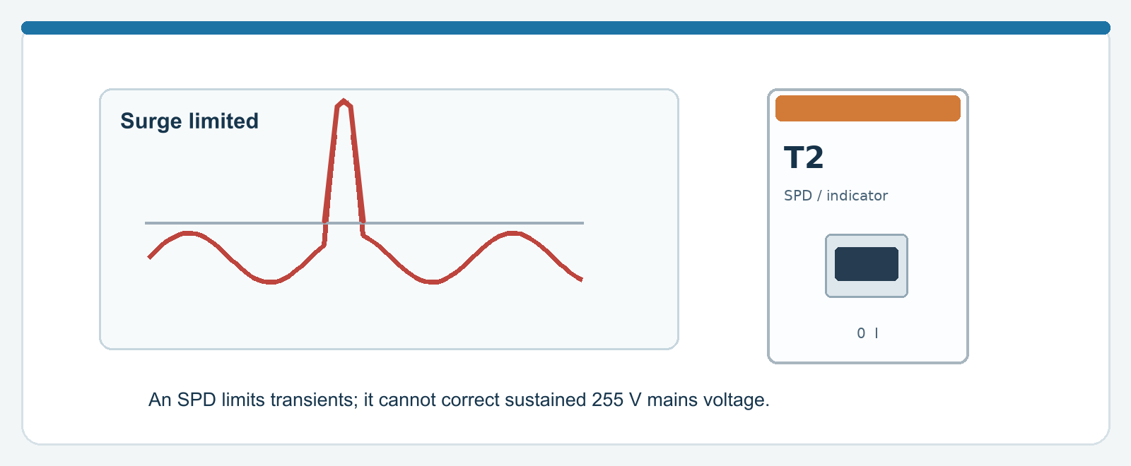
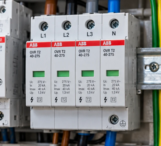
A surge protective device (SPD) limits brief voltage transients, for example from switching or lightning effects. It is not a voltage regulator and does not solve prolonged mains voltage above the standard limit.
Types 1, 2 and 3
These classes describe different applications and test methods. Type 1 relates to particular lightning-current requirements, type 2 to surge limitation in a distribution assembly, and type 3 to supplementary protection near equipment.
What is inside?
Many SPDs contain components that conduct strongly above a certain voltage, such as varistors or gas-discharge devices. This limits a transient. An SPD may need replacement after a severe event.
Status indicator and upstream protection
Many modules have a green/red status window. A defective SPD or an end-of-life indicator calls for inspection. Connection method, earth connection and any required upstream protection follow from the design.
Warning: An SPD cannot prevent all damage and must never be regarded as a substitute for earthing, equipotential bonding and a safe installation design.
18. PV in the distribution board: current in two directions
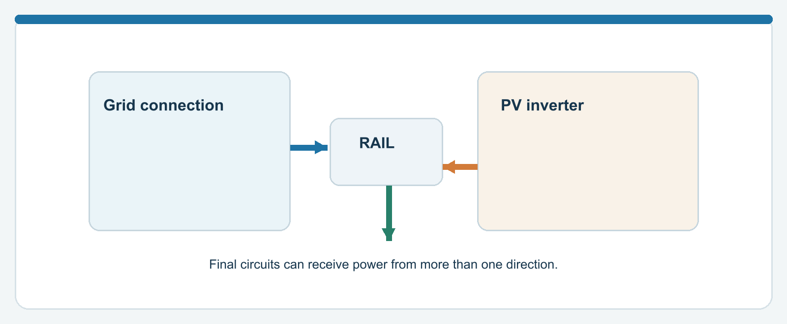
In a traditional home, power generally flowed from the mains connection to final circuits. Solar panels can introduce energy at a second point. That changes current distribution in parts of the board.
Not every busbar section carries the same current
When loads and generation connect to the same distribution point, different rail sections can carry different currents. The main fuse does not automatically limit every local combination of currents on the rail.
Inverter protection is a design decision
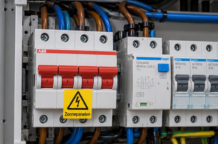
The connection point, circuit protection, RCD choice, means of isolation and manufacturer instructions determine how PV should be incorporated. Even an inverter that regulates its own output may impose requirements on protection and isolation.
A contactor does not create a PV circuit
A Shelly and contactor arrangement may switch off a PV installation according to electricity prices, for example. It does not add protective functions: the underlying installation must be independently safe.
Warning: AC feed-in and multiple supplies require assessment of the entire distribution assembly under the applicable product and installation rules.
19. Contactor versus smart relay
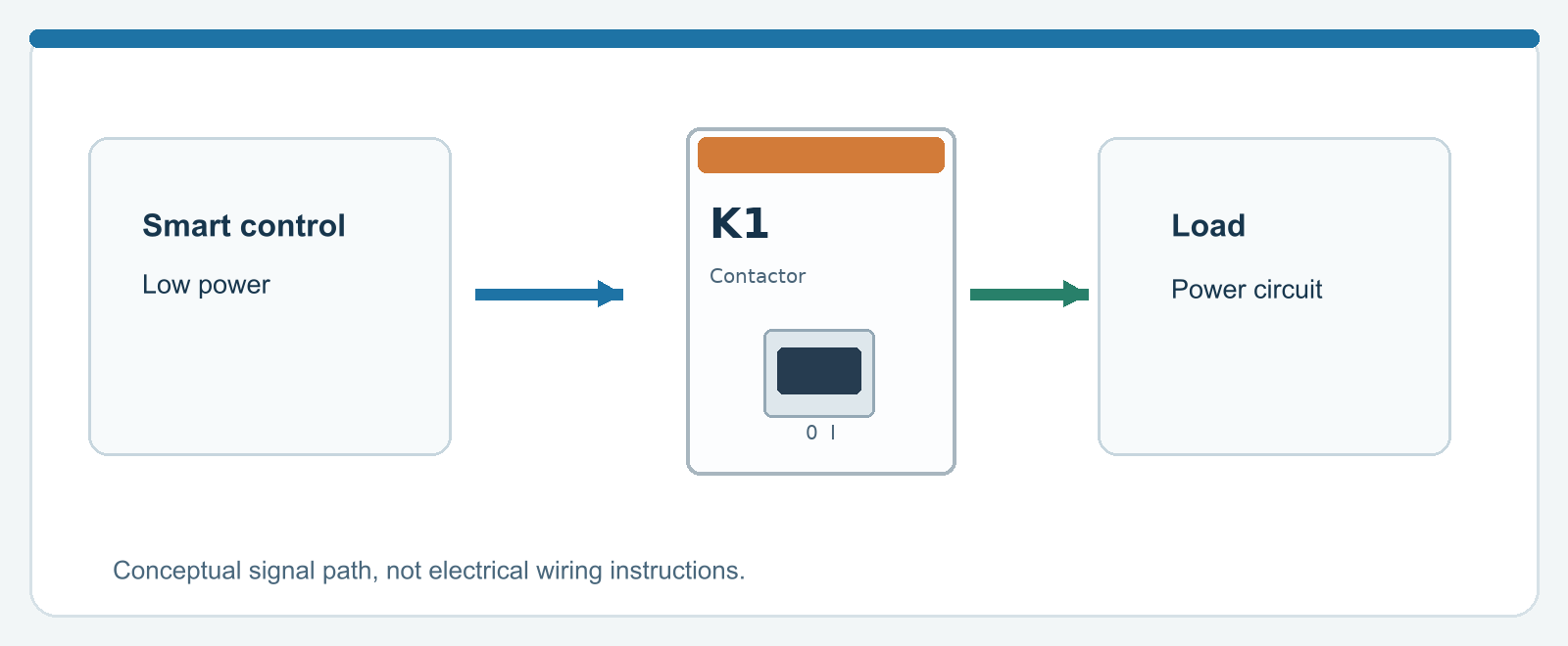
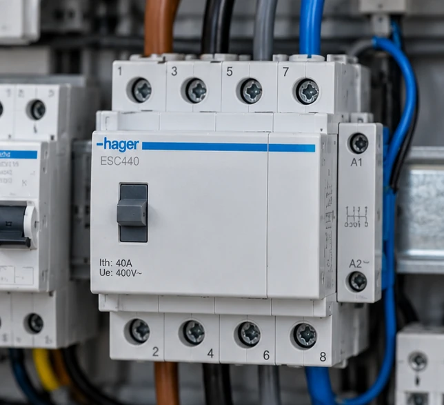
A relay inside a smart module is not the same as a contactor. A contactor is generally designed to switch electrical loads through a separately operated coil. Intelligence lies in the control, not in the power contacts.
Separate control and power
A Home Assistant command may operate a relay output that drives a suitable contactor coil. The contactor then switches the power circuit for which it is designed. The desired resting state follows from an explicit fail-safe analysis.
AC-1 is not every kind of load
A contactor’s current rating depends on utilization category, supply voltage, switching frequency and load characteristics. Motors and capacitive loads have different requirements from a purely resistive load.
Manual operation and feedback
The status of a smart module does not always prove that its power contacts are actually open. Critical functions may require suitable auxiliary contacts and fault monitoring.
Warning: Smart home automation must never take over electrical protection. The electrical installation must remain safe during network outages.
20. Energy metering per circuit: what do you see?
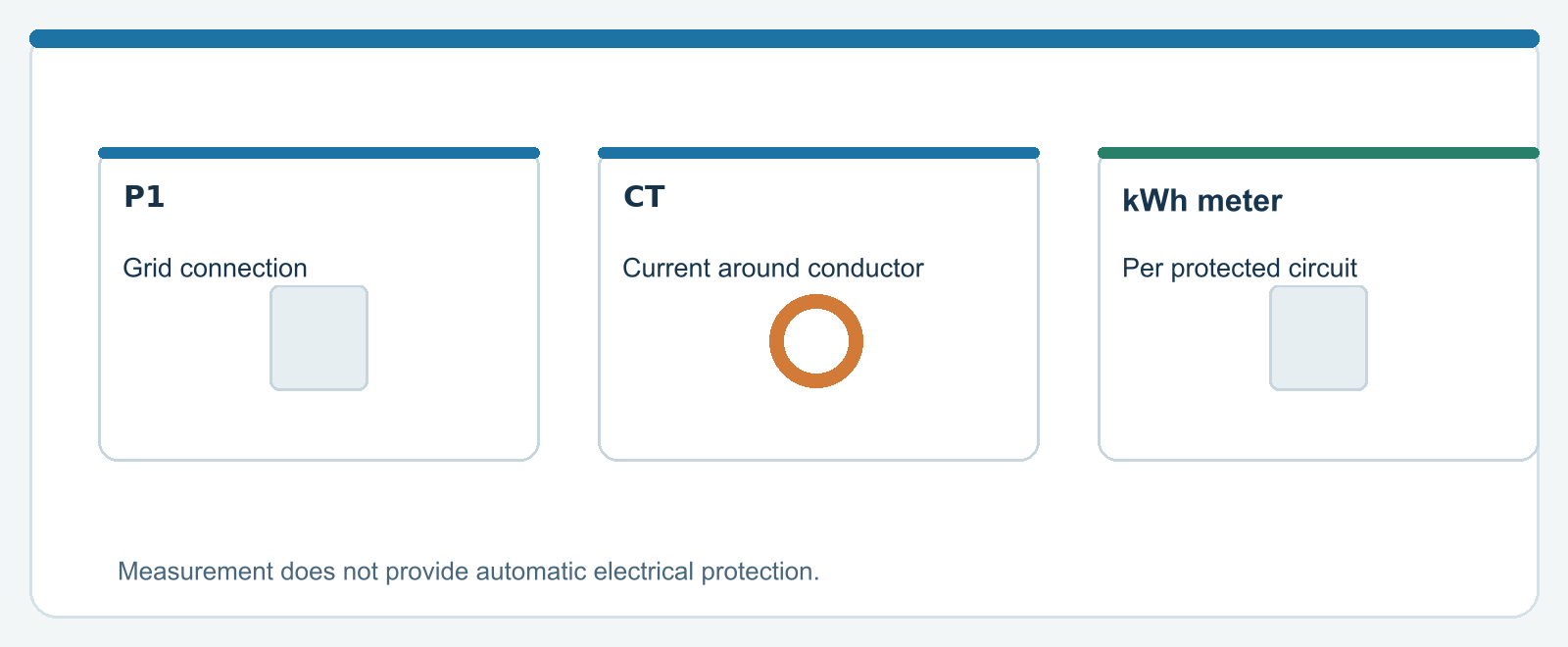
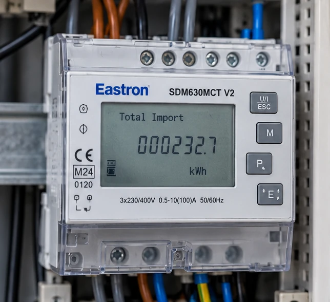
DIN-rail meters and current transformers can show the consumption of one or more circuits. A P1 smart-meter connection mainly shows energy flows at the grid connection. These measurements complement one another.
P1: the overall picture
With suitable equipment, P1 data shows import and export at the connection point. It does not automatically identify which device caused a peak.
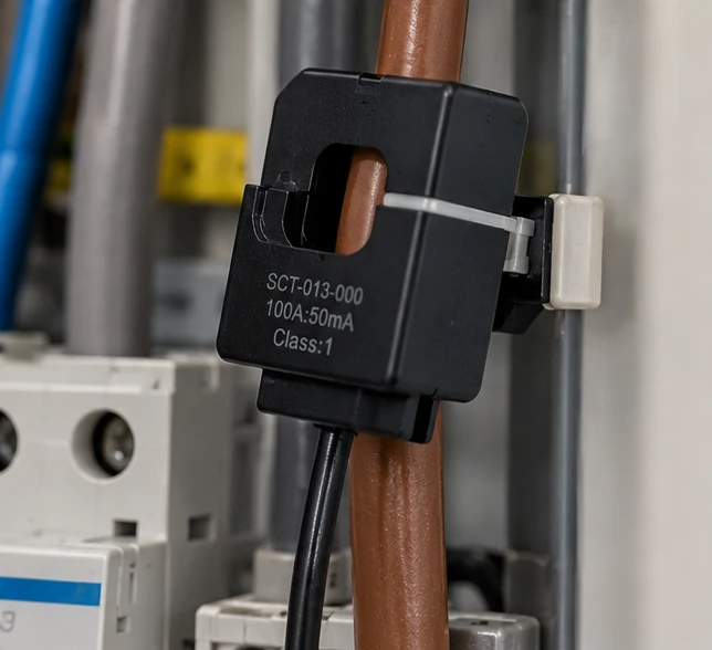
CT clamp: measuring current without routing the load through the meter
A current transformer measures the magnetic field around a conductor. Electronics convert this to a reading; accurate active power may also require voltage measurement and phase-angle information.
Direct kWh meter
With a direct energy meter, the intended circuit passes through a meter certified for that use. Both approaches have limits, for example at low loads, high currents or with an incorrect sensor configuration.
Warning: Measurement is not protection. An energy meter does not replace an MCB, RCD or correct wiring.
21. Adding EV charging, a heat pump and a home battery
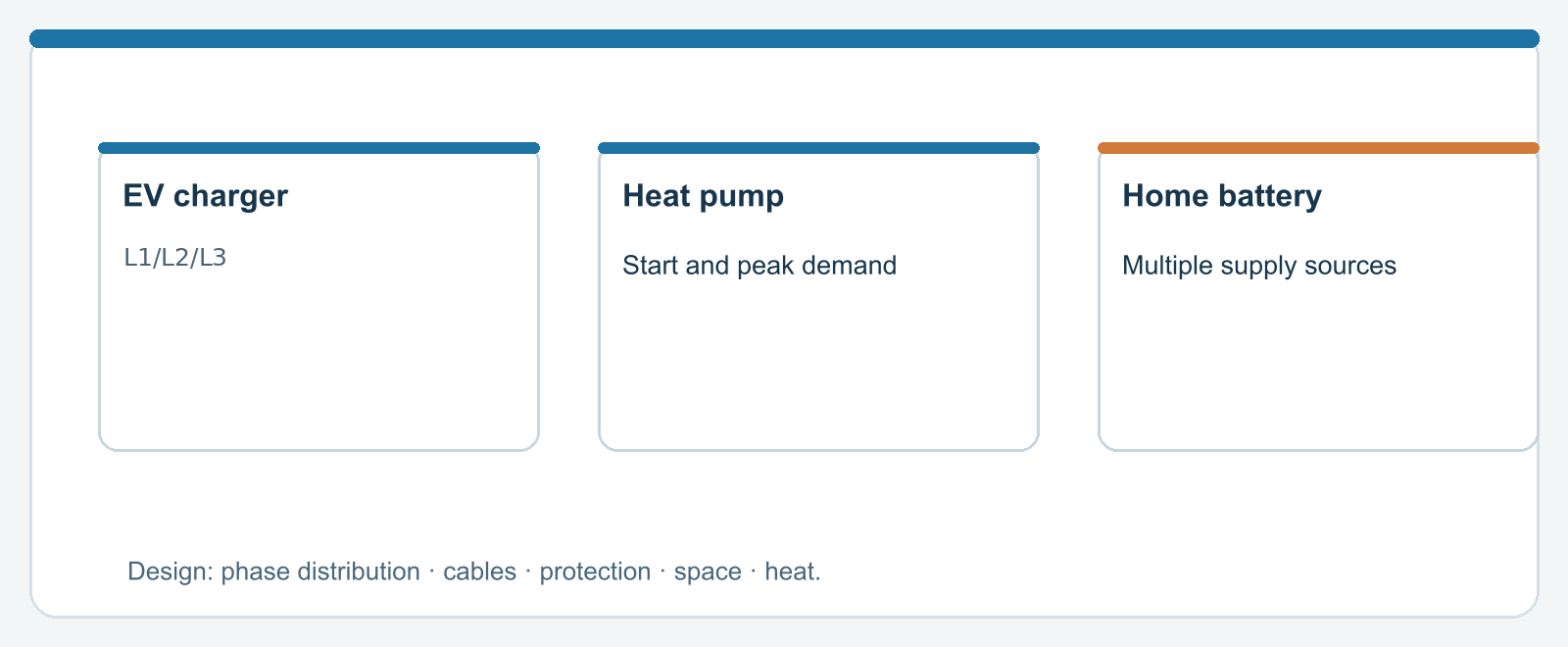
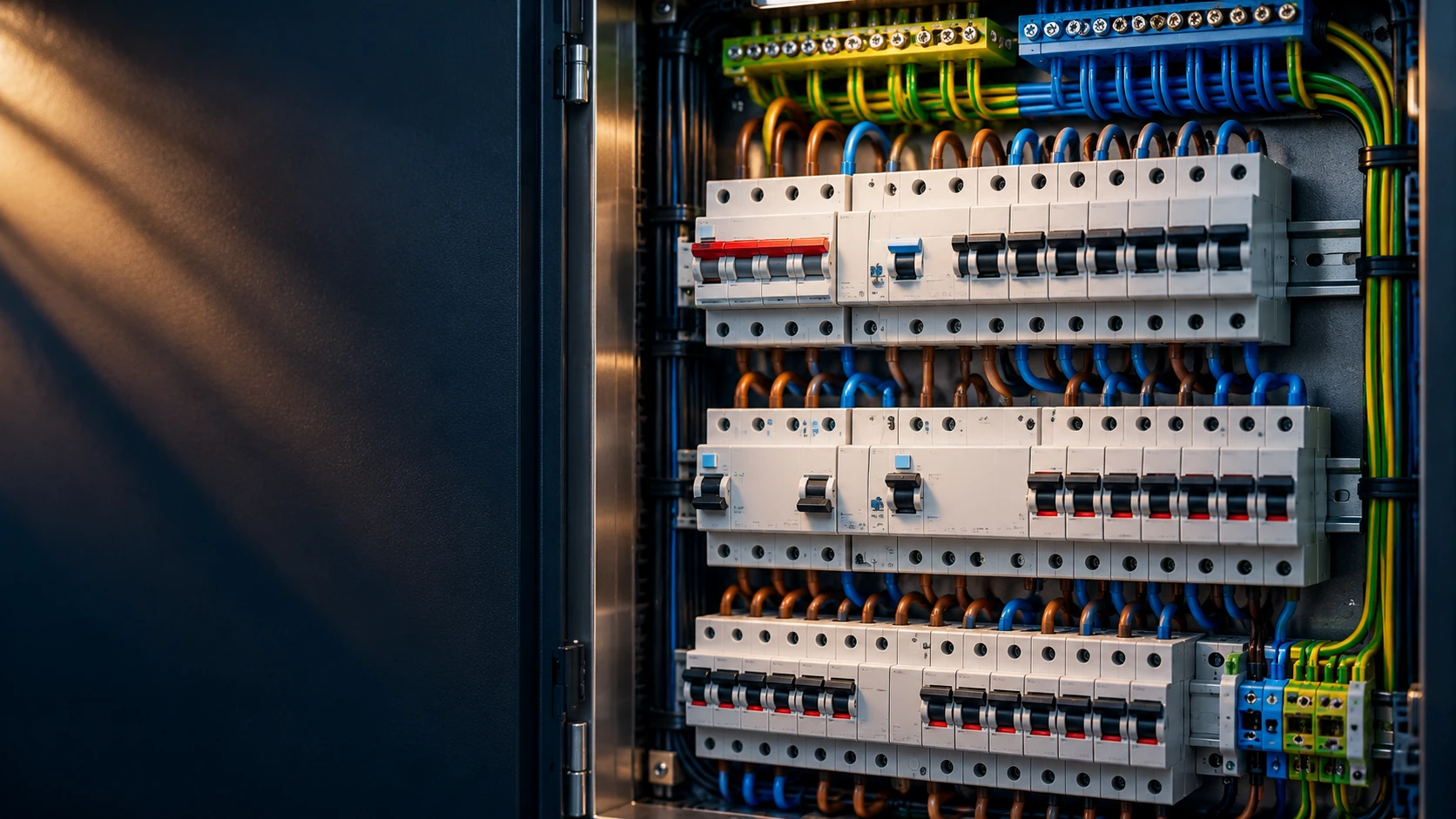
Modern distribution boards serve ever more purposes. Cooking, charging, heating, solar generation and battery storage require a coherent design and sufficient space for operation, protection and heat dissipation.
EV chargers
An EV charger can draw a high current for a long period. Load balancing does not automatically prevent every fault and does not replace suitable protection against overcurrent and DC residual currents.
Heat pump and boiler
Inrush currents, power demand, electric backup heating and possible consumption per phase need attention. Smart scheduling can reduce peaks but must not compromise installation safety.
Battery storage and backup power
A home battery with backup functionality needs a transfer concept that cannot inadvertently parallel the backup supply with the grid. Some installations can supply only selected circuits during a grid outage.
Warning: Assessing an extension also means checking the existing enclosure, rails, main switch, spare positions, heat and documentation.
22. What can you safely notice?
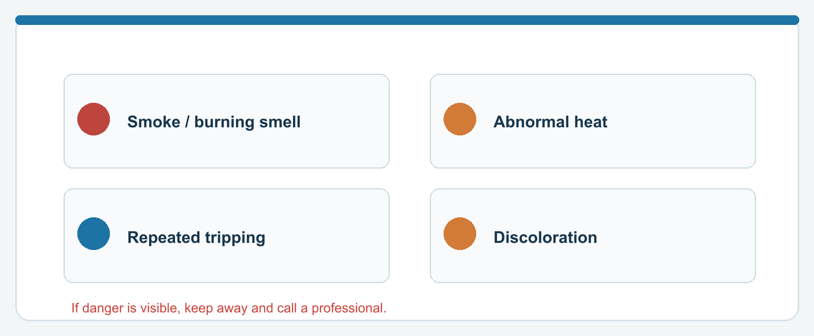
A resident need not open the board to notice that something may be wrong. Repeated tripping, unusual heat, humming or crackling, and discoloration are warning signs to take seriously.
What you can inspect
Check circuit labels, visible status windows, switches intended for normal operation and any fault messages. Keep the area around the board accessible and dry.
When to stop immediately
A burning smell, smoke, sparks, visible melting or abnormal noise calls for keeping your distance and obtaining professional help. Do not operate a switch when that feels unsafe or damage is already visible.
Repeated tripping
Record which device and circumstances coincide with the fault. Have the cause determined instead of bypassing protection or repeatedly resetting it.
Warning: RCDs and circuit breakers are protective and warning components, not fault remedies. The underlying fault persists until it is corrected.
23. What an installer checks after a modification
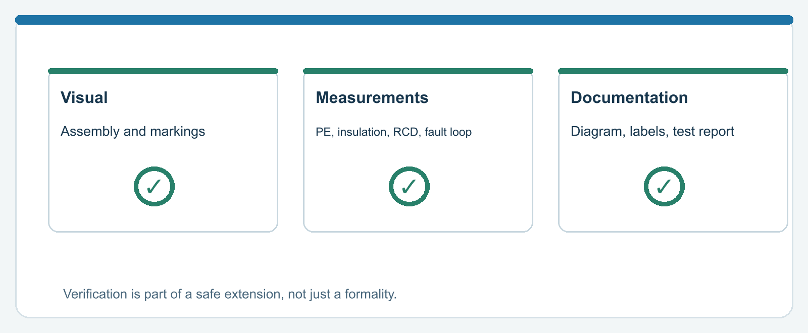
A technically correct distribution board is more than a neat row of modules. After construction or extension, it must be demonstrated that the protection and installation suit the connected circuits and expected fault conditions.
Documents and visual inspection
This includes an up-to-date circuit schedule, suitable product combinations, correct marking, appropriate conductor sizes, correct earth and neutral arrangement, and clear indication of multiple supplies.
Measurements and tests
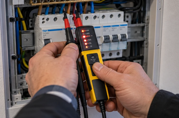
Depending on the modification, checks may include protective conductor continuity, insulation resistance, polarity, fault-loop impedance, RCD operation and switching functions.
The complete assembly matters
Adding a single module may change the composition of the distribution assembly. Product standards and system documentation are therefore as important as the electrical installation standard.
Warning: After an extension, request an updated diagram or circuit list and the relevant test and verification data.
Sources and standards status
Consulted on 28 October 2026. This technical explanation is original and does not reproduce copyright-protected clauses from standards.
- NEN: NEN 1010:2020+C1:2024 — low-voltage electrical installations
- NEN: NEN-EN-IEC 61439-3:2024 — distribution boards intended for operation by ordinary persons
- NEN: NEN 3140:2011+A3:2019 — safe work on low-voltage electrical installations
- NEN: NEN 1010-8:2026 — functional aspects
- NEN: NPR 5310:2024 — practice guideline for NEN 1010
- ABB: Thermal-magnetic miniature circuit breaker explained
- Hager: Example technical ratings for a 40 A/30 mA Type A RCCB
- Eaton: RCD Type F: behavior with mixed frequencies
- MechScript: Basic article: The home distribution board explained
Important: The latest published standards and their legally designated editions are not necessarily the same. For a specific project, check the Omgevingsregeling, Bbl and applicable standards.
None of the images is a wiring manual.