
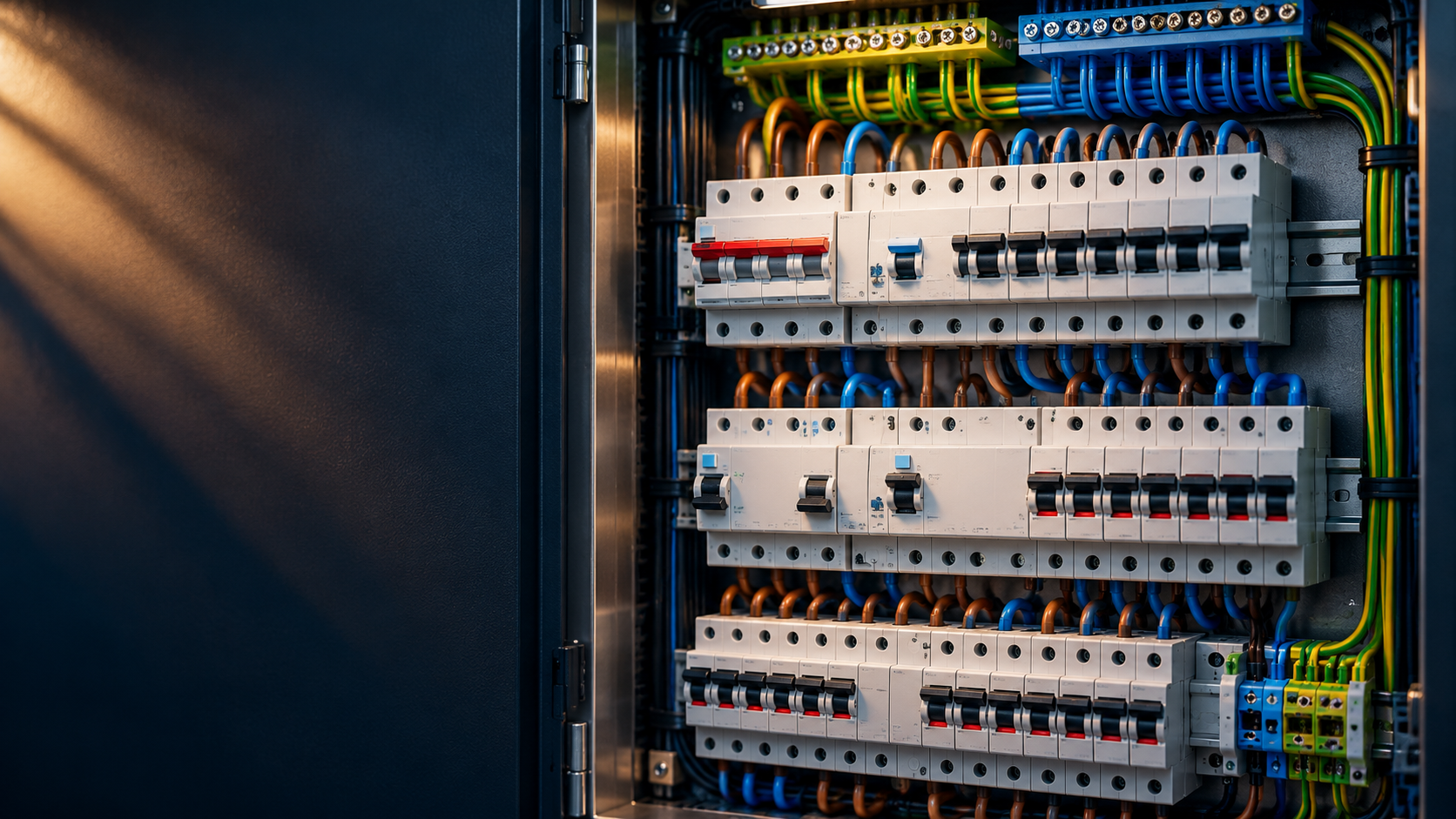
Technical guide — October 2026. This article is educational; the illustrations are not wiring diagrams. Work on a distribution board is for competent personnel.
1. What you will learn and what you should not do yourself
The distribution board is the central distribution assembly in a home. It brings together the electricity supply, protection against electrical faults and modern applications such as solar panels, EV chargers and energy meters. This article explains the complete system: not just the names of the components, but above all why they are there and what happens under fault conditions.
Who is this guide for?
For interested homeowners, Home Assistant users and technically minded readers who want to understand an installation or discuss an extension with their installer. We explain the technology accessibly while using the correct electrical terms.
The most important boundary
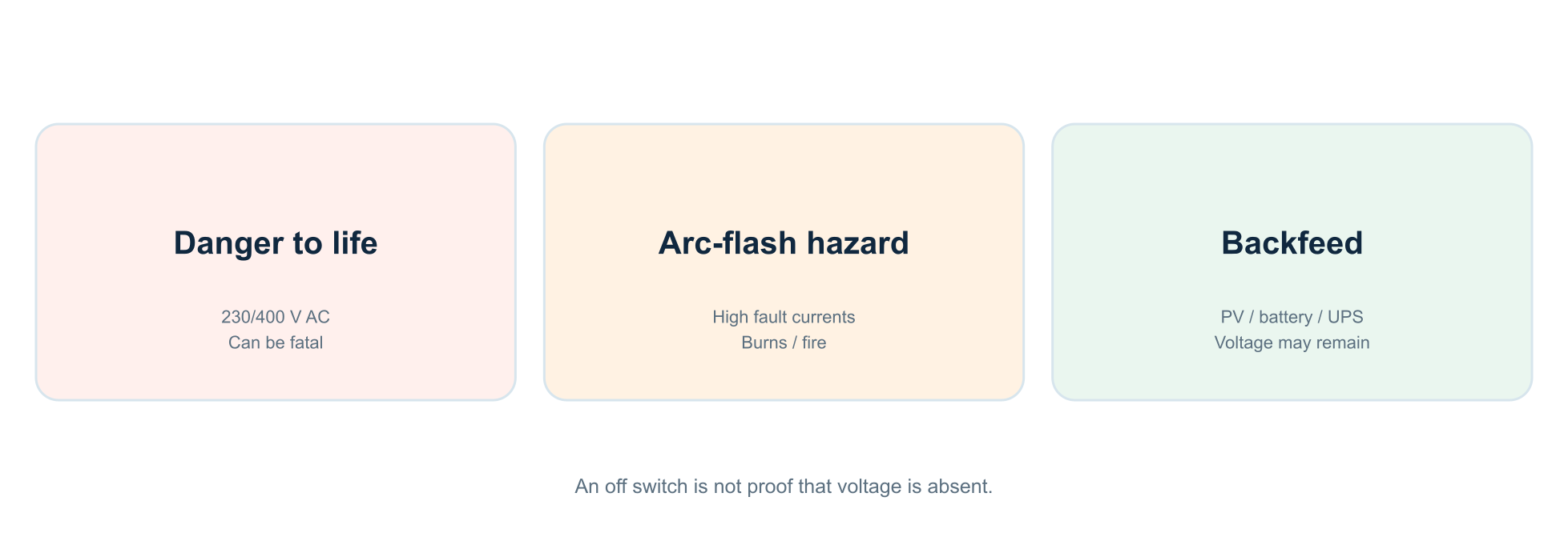
A distribution board is not a safe practice object. Live parts may be present behind an opened cover, even when certain switches are off. High short-circuit currents can cause an arc flash, vaporised metal or fire within milliseconds. PV, a home battery or a UPS can mean there are multiple power sources.
⚠️ Safety boundary: this article contains functional diagrams, not executable wiring plans. Opening, extending, wiring, testing or measuring active parts is work for a competent person using an appropriate procedure, equipment and verification.
What is normally acceptable for a resident?
Identify circuits from the outside, keep the circuit schedule up to date and operate accessible controls in accordance with the manufacturer’s instructions. In the event of repeated trips, moisture, fire damage, heat or a burning smell: switch off if it is safe to do so, keep your distance and call an electrical installer.
2. Which NEN standard applies in 2026?
The edition describing the current state of the art and the edition legally designated through building regulations are not automatically the same. Online articles often get this distinction wrong.
NEN 1010 and the Building Works Environment Decree
NEN 1010 is the central standard for the design, installation, extension and verification of low-voltage electrical installations. The current main publication at NEN is NEN 1010:2020+C1:2024. Since 2026, NEN 1010-8:2026 has also covered functional aspects, including energy efficiency, generation and storage. NEN 4010:2024 is a more accessible practical standard for many common situations.
Legal designation: check the edition
The Bbl (Besluit bouwwerken leefomgeving) sets safety requirements and refers to NEN 1010. Annex II to the Omgevingsregeling specifies which edition is designated, along with limitations on its application. An early-2026 review still named 2015 + C2:2016 + A1:2020 as the designated edition; the availability of 2020+C1:2024 does not automatically make it legally designated. For a particular building project, a qualified professional must check the current consolidated regulation and its scope.
Other relevant standards
-
NEN 3140:2011+A3:2019: operation, safe work, maintenance and inspection. A 2026 draft has been published; a draft does not automatically replace the final standard.
-
NEN-EN-IEC 61439-3:2024: assembled distribution boards intended for operation by ordinary persons. The complete enclosure and component combination must be suitable as a system.
-
NPR 5310:2024: a code of practice explaining NEN 1010; it is not an independent replacement installation standard.
⚠️ Standards warning: this guide paraphrases principles and does not reproduce clauses from standards. Exact requirements vary with the situation, system, year of construction, applicable edition and risk assessment. Version check: 15 October 2026.
3. Voltage, current, power and energy
A safe design begins with four quantities that discussions about distribution boards often conflate.
Four different concepts
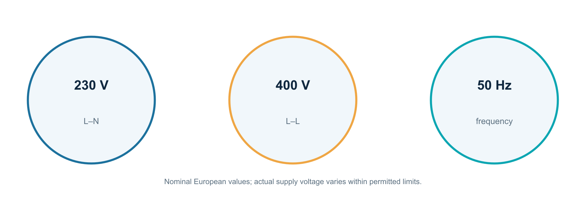
Voltage (V) is the potential difference that can cause current to flow. The usual nominal mains voltage is 230 V between phase and neutral and 400 V between two phases. Current (A) is the amount of electric charge flowing per unit of time. Power (W) describes consumption at a given moment; energy (kWh) is power integrated over time.
For a purely resistive single-phase load, approximately P = U × I. A 2,300 W kettle draws roughly 10 A at 230 V. Motors and electronic power supplies also involve power factor, harmonics and inrush current, so simply dividing watts by 230 is not always sufficient.
What does 16 A mean?
A circuit with a B16 breaker is not an energy budget of exactly 3,680 W at all times. Its thermal time–current characteristic determines when it trips under overload. Cable cross-section, installation method, ambient temperature, grouping and termination technique also limit the permissible current.
⚠️ Danger to life: 230 V AC can be fatal. Contact can cause cardiac arrhythmia, respiratory arrest, muscle spasms or secondary injuries. The hazard depends not on voltage alone, but also on the current path, duration and circumstances.
4. The current path from grid to socket
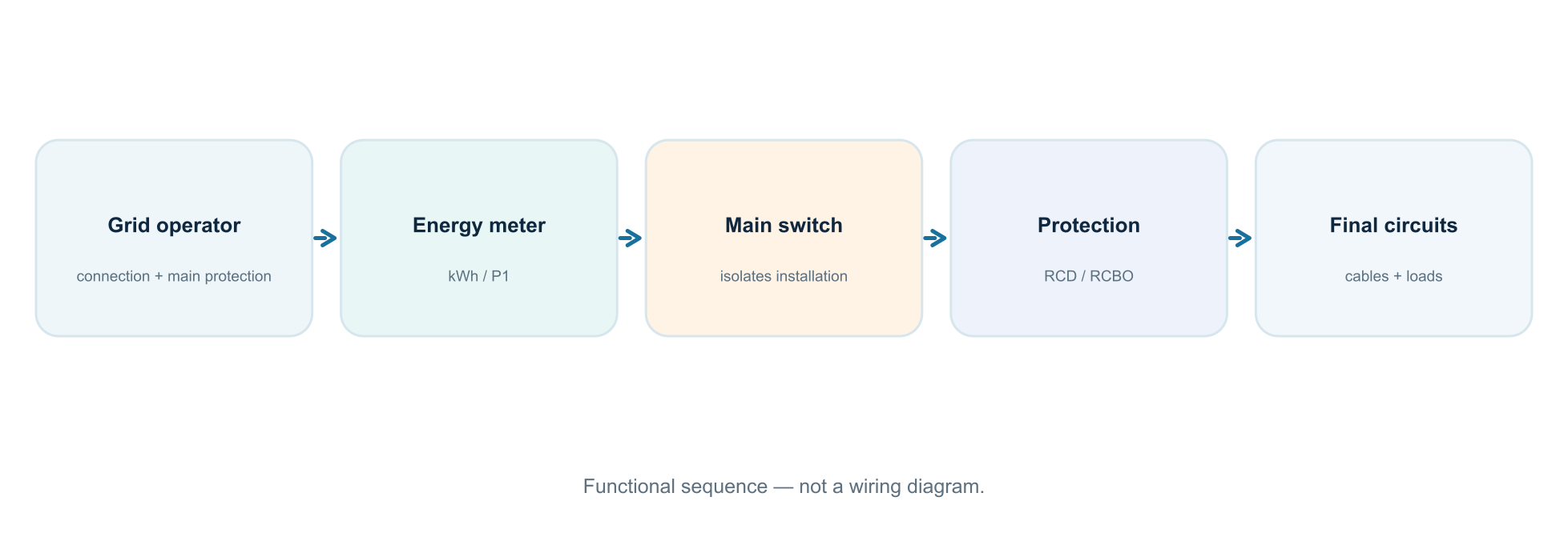
A distribution board has a logical structure: first the grid operator’s connection, followed by the customer installation with isolation, protection and distribution.
Who owns what?
The grid operator normally manages the grid connection, main protection and meter under the connection conditions. The building installation starts at the relevant handover point; the precise boundary and ownership are not identical for every connection. A sealed main fuse is not an ordinary user-operable component.
Inside the board
The main switch enables the installation to be isolated. Circuits are then divided through residual-current devices, miniature circuit breakers and/or combined residual-current circuit breakers. Surge protective devices, energy meters, contactors and communication components may also be present.
A final circuit is an electrical circuit
A final circuit supplies a particular part of the installation, such as lighting and sockets, the kitchen, a heat pump or an EV charger. The number of circuits alone says nothing about the quality of the distribution. The design must remain safe under fault conditions and after future changes.
Why functional diagrams?
Real wiring depends on device types, connection direction, supply points, neutral allocation and manufacturer instructions. A generic sketch connecting wires arbitrarily to a module can create dangerous false confidence.
5. Single-phase or three-phase: in practice
Dutch homes may have a single-phase or three-phase connection. The difference is more than the number of wires.
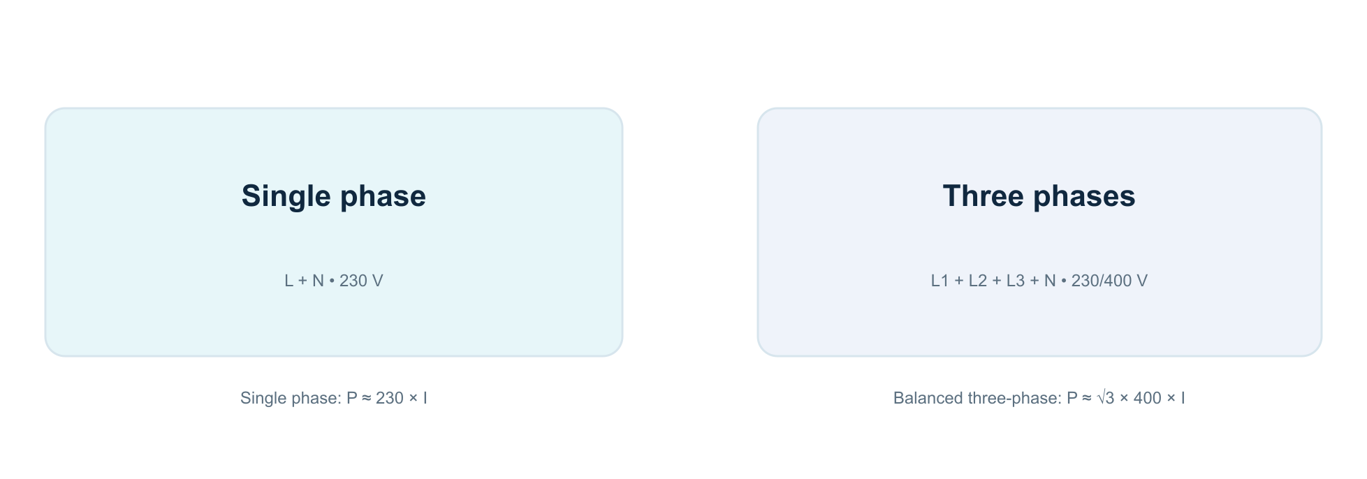
Single phase
A single-phase connection uses one active phase and neutral. At 1×35 A, the calculated apparent connection capacity is about 230 × 35 = 8.05 kVA. The actual continuous power available also depends on the load and protection; peak loads have different limits.
Three phases
With 3×25 A, three phases are available. For a balanced, nearly resistive three-phase load, total power is approximately √3 × 400 × 25 = 17.3 kW. Each phase remains individually limited by its own main protection: 25 A on L1 is not offset by 5 A on L2.
Do not simply add three times 230 V
Between L1 and neutral there is nominally 230 V; between L1 and L2 about 400 V. This is because the three sinusoidal voltages are 120 degrees apart in phase. Equipment designed for 400 V needs the appropriate connection, protection and documentation.
Distribute loads wisely
Where practical, spread larger single-phase loads across different phases. The key control variable is not just total kW, but current on each phase over time.
6. Main fuses, meter and sealed parts
Main protection is a different protective level from a breaker on a final circuit.
Main protection
A grid connection has main protection, such as cartridge fuses or another protective arrangement used by the grid operator. Its type and rating depend on the connection. Main protection may need to interrupt higher fault currents than a single final-circuit device.
Why not break the seals?
Connection equipment may be the grid operator’s responsibility, be sealed, and lack adequate touch protection once opened. Connection conditions and authorisations govern access. Removing seals or manipulating main fuses is not a normal task for residents.
The smart meter is not a circuit breaker
The electricity meter records energy flows and often provides a P1 interface. Some meters have an internal switching facility, but this must not be equated with an isolator or protective device for final circuits.
In practice
An upgrade from one to three phases may require changes both to the main connection and to the customer’s distribution assembly. Installing a new meter does not automatically make the rest of the installation suitable.
⚠️ Important: if the main protection trips, the situation is fundamentally different from a tripped circuit breaker. Have the cause investigated by the authorised party.
7. The main switch: what does it switch, and what does it not?
The main switch is primarily intended for isolation and operation, not for independently detecting a short circuit or earth leakage.
Function
A suitable, correctly applied main switch can interrupt the active conductors of the downstream installation that need to be isolated. A three-phase installation often has a four-pole device; the precise switching arrangement depends on the installation and earthing system.
40 A is not automatic trip protection
The 40 A or 63 A marking on a main switch normally denotes its rated current capacity under specified conditions. It does not mean the switch automatically trips when 40 A is reached. Other protective devices are needed for that.
Special case: backfeed
A PV inverter or home battery may be connected locally to the distribution board. It must therefore be clear which parts actually become de-energised when a particular switch is operated. A main switch on the grid side does not necessarily physically disconnect every possible energy source.
Operating a switch is not measuring
Moving a switch to ‘off’ does not prove that an open board is safe. Before work, competent personnel verify absence of voltage using the intended procedure.
8. How a residual-current device works
A residual-current device (RCD) compares current in all active conductors of the monitored circuit.
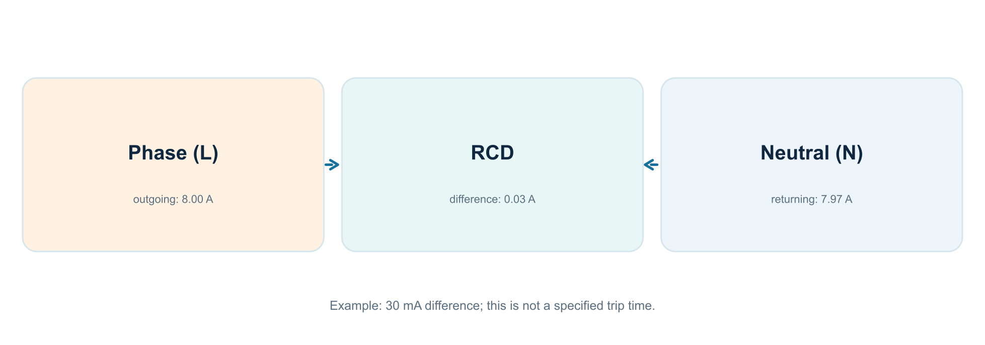
The sum of the currents
In normal operation, the vector sum of outgoing and returning currents is virtually zero. A fault path through earth or a person can create a residual current. On a 30 mA RCD, the rated residual operating current IΔn is 0.03 A. That does not guarantee an immediate trip at exactly 30.000 mA.
What does an RCD protect against?
A suitable RCD provides additional protection against certain electrical faults and can help reduce fire risk from leakage currents. It cannot prevent electric shock in every situation. A person touching phase and neutral simultaneously may, for example, create a current path that the RCD does not see as an imbalance.
Test button
The T button creates an internal test imbalance while the RCD is appropriately energised. Test according to the manufacturer’s instructions and restore supply only if the cause of an unexpected trip is clear. The T button does not replace measurement-based verification of operating currents and times.
⚠️ Note: a 30 mA RCD must never be regarded as permission to touch live parts.
9. RCD types AC, A, F and B are not interchangeable
Modern electronics and power electronics can produce leakage currents with different waveforms. This makes RCD classification important.
Which waveforms can be detected?
Type AC is intended for purely sinusoidal alternating residual currents; in modern applications this is often inadequate. Type A is also designed for pulsating DC residual currents within its specifications. Type F addresses certain mixed frequencies, for example in selected single-phase drives. Type B additionally covers suitable smooth DC residual currents and other frequency components within the product specification.
PV, EV and inverters
A PV inverter, variable-frequency drive or EV charging device may impose specific RCD requirements. Sometimes type A is permitted because of the equipment’s characteristics; sometimes another type or additional DC fault-current monitoring is needed. Assess this against installation rules and the connected equipment’s documentation.
Rated current versus residual current
An RCD marked 40 A / 30 mA has two entirely different ratings: 40 A is its rated current; 30 mA is the rated residual current for the protective function. A suitable coordinated design must protect the RCD from overload.
⚠️ Common mistake: ‘there is a 30 mA RCD’ says nothing about the correct type, upstream protection, number of circuits, selectivity or operation in the presence of DC components.
10. The circuit breaker: B16, C16 and other markings
A miniature circuit breaker (MCB) combines a thermal overload function with a fast electromagnetic short-circuit function.
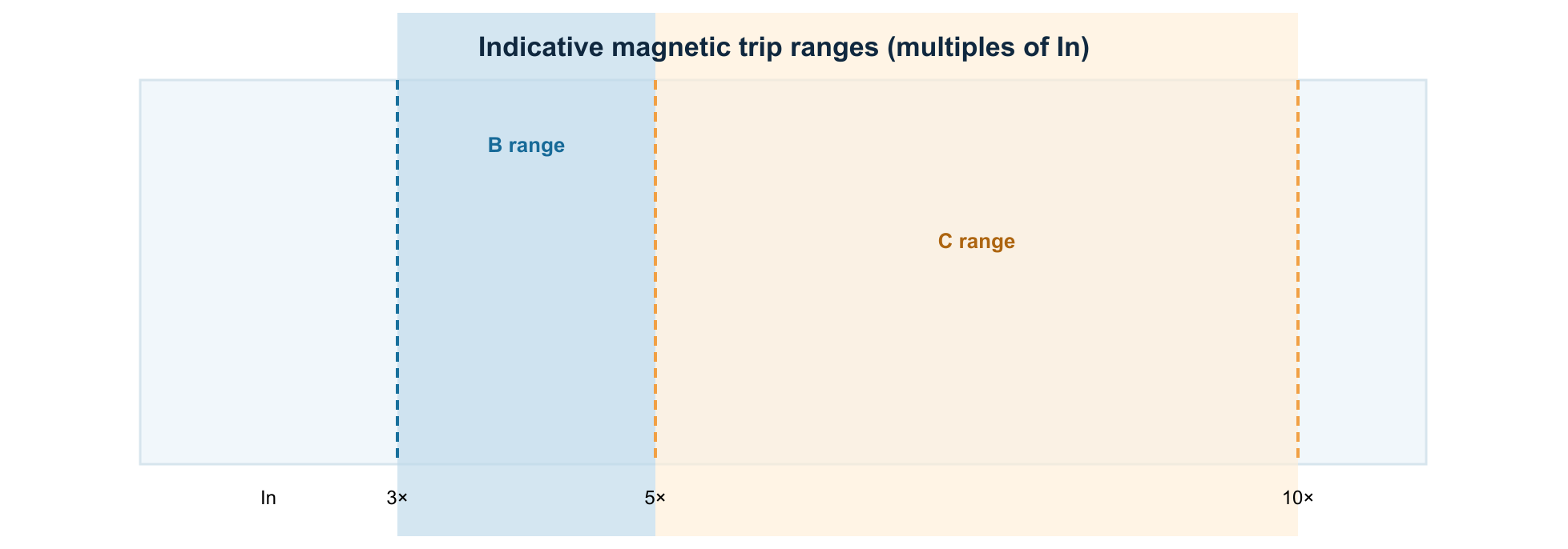
Thermal and magnetic
A small, sustained overload is assessed thermally: the breaker does not have to trip at the exact second In is exceeded. At high fault currents, the magnetic function acts quickly. A B characteristic typically has a magnetic operating range of approximately 3–5 × In; a C characteristic 5–10 × In. The exact time–current curve depends on the product standard, manufacturer and conditions.
Why C16 is not ‘stronger’ than B16
Both are rated at 16 A. A C16 tolerates certain higher inrush currents without immediate magnetic tripping, but generally needs a higher available fault current to guarantee fast disconnection. A long cable run or relatively high loop impedance can make this an unsuitable choice.
What does 6 kA mean?
A marking such as 6000 or 6 kA refers to the stated short-circuit breaking capacity under the relevant product standard, not the maximum permissible operating current. It must suit the expected short-circuit current and permitted coordination with upstream protection.
11. RCD plus breaker, or a combined RCBO?
Two common ways to protect final circuits look similar but affect outages, available space and fault-finding differently.
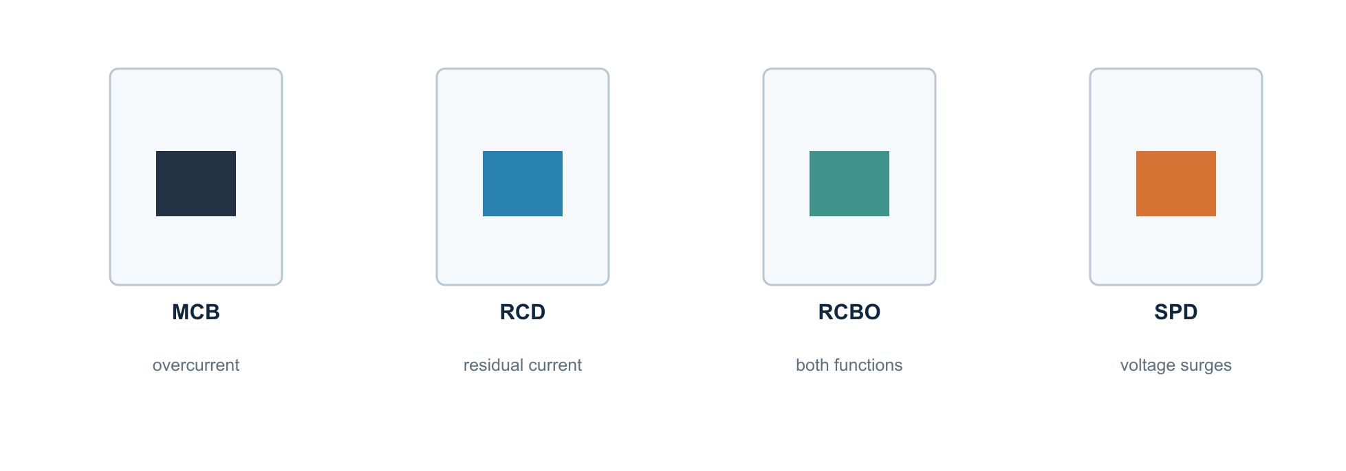
Option A: shared RCD plus multiple breakers
One RCD monitors several downstream circuits, while each circuit has its own MCB. The design must account for combined leakage currents, reliability, rated currents and functional subdivision. A fault in one appliance can disconnect more circuits.
Option B: individual RCBO
An RCBO combines residual-current and overcurrent protection for its own circuit. This often confines a fault locally and makes circuits more independent. Compact RCBOs can make the board easier to follow, but the choice must suit the distribution system used.
Number of circuits per RCD
The familiar rule of thumb ‘a maximum of four circuits per RCD’ is not a universal current standard formula. The designated standard edition, configuration, expected leakage currents and design criteria determine the applicable conditions. Do not use an absolute number without standards context.
Practical choice
In modern extensions, an RCBO per final circuit is often attractive for availability and fault localisation, but not every board can be converted without consequences.
12. Short-circuit current, loop impedance and disconnection time
Protection works only if the entire path from transformer to fault location is sufficiently well understood electrically.
What happens during a short circuit?
Low impedance between active conductors can produce a very high fault current. This causes large electrodynamic forces and rapidly rising heat. A protective device must be able to interrupt the fault, both in breaking capacity and permitted disconnection time.
Loop impedance Zs
A fault current runs through a loop with resistance and reactance: transformer, cables, joints and possibly protective conductors. Higher loop impedance limits current, so a breaker may fail to operate within the required time. Characteristic selection therefore cannot be separated from the installation.
Do not check only the B16
An installation requires coordination among cable, MCB, RCD, main protection and earthing system. Special supplies, such as an inverter with limited fault-current delivery, can also affect fault response.
⚠️ Safety: checking fault-loop impedance and short-circuit conditions requires suitable test equipment, adequate expertise and a formal verification method. Never create short circuits to ‘test’ a protective device.
13. Selectivity: why the right circuit does not always trip alone
Selectivity means that, in a fault, preferably the protective device nearest the fault operates without unnecessarily disconnecting larger parts of the installation.
Two levels
At modest overloads, differing ratings and characteristics can yield logical behaviour. Selectivity is harder during a solid short circuit: multiple protective devices see very high currents at the same time. Full selectivity must be demonstrated using product data, curves or manufacturer tables.
Example: B16 behind main protection
It is not guaranteed that only the B16 trips. A high fault current may also operate upstream protection, depending on device type, time–current characteristic and selectivity conditions.
Back-up protection and cascading
Some manufacturers permit particular combinations in which an upstream protective device supports the breaking capacity of a downstream device. Components cannot simply be interchanged. This belongs in a documented design with verified combinations.
Availability as a design goal
Distribute vulnerable loads across independent protection, for example network equipment, medical support or critical heating controls. Never design for availability at the expense of electrical safety.
14. Neutral and protective conductors
The blue neutral conductor and green/yellow protective conductor have fundamentally different functions.
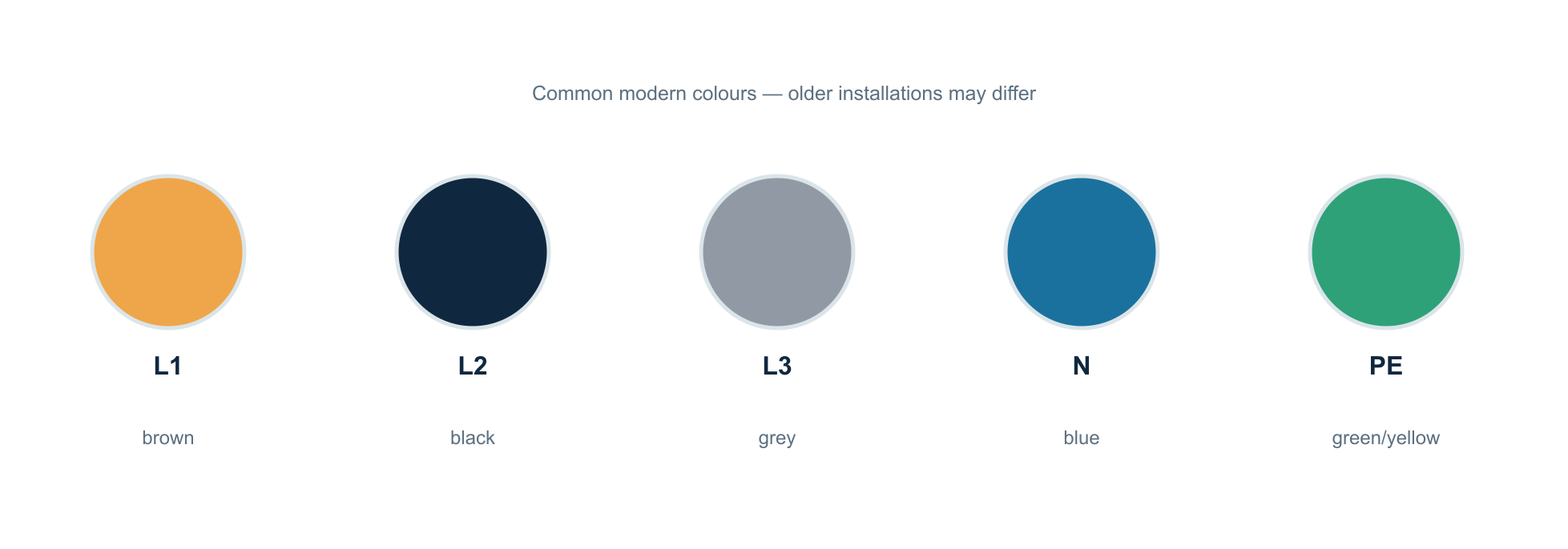
Neutral (N) normally carries operating current
For a single-phase load, neutral normally completes the return path. In a balanced three-phase system the sum current can be small, but neutral is not inherently current-free. Imbalance and non-linear loads can add further effects.
The protective conductor (PE) is a safety provision
PE connects exposed conductive parts to the protective system. In normal operation, it should not serve as an ordinary return conductor for load current. Protective equipotential bonding connects relevant metal parts to limit dangerous potential differences.
Why neutrals are not interchangeable
A circuit passing through an RCD must route the corresponding active conductors correctly through that same device. A neutral from another RCD zone, or an incorrectly shared neutral, can cause unwanted tripping, fault conditions and unsafe situations.
Neutral interruption on three phases
An unintended neutral break in an unbalanced three-phase system can create dangerous voltage distribution across single-phase loads. Sensitive equipment may be damaged and the situation can be life-threatening.
15. Earthing, bonding and TN/TT systems
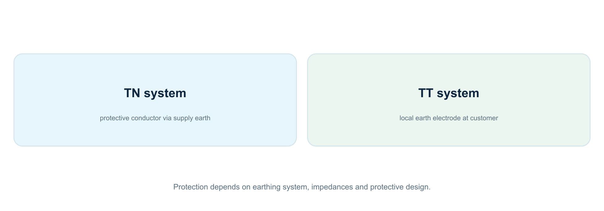
An earth electrode is not the same thing as a green/yellow wire; the earthing system also determines which fault-protection measures are required.
TN system
In a TN system, the protective conductor is connected to the earthed supply point in a defined way. An insulation fault can create a relatively low fault impedance, allowing overcurrent protection to operate under the right conditions. The exact configuration, such as TN-C-S, determines requirements for PEN, PE and N.
TT system
In a TT system, the customer has an earthing arrangement for exposed conductive parts that is independent of supply earthing. Earth fault current may be too low for an ordinary breaker to operate quickly; residual-current protection is therefore often essential to meet the required fault protection.
Earthing must be measured, not guessed
Earth electrode resistance, PE continuity, protective bonding, earth-fault impedance and the chosen protection form a coherent whole. An earth rod alone is not proof of safety.
⚠️ Warning: connecting an ‘extra earth’ yourself to neutral, water pipes or arbitrary metalwork can create life-threatening fault paths. Have an installer identify the earthing system.
16. DIN rail, busbar, neutral bar and earth bar
The plastic enclosure is not a neutral box to which unlimited loose components can be added. It is an assembled distribution board.
DIN rail
Miniature breakers, RCDs, contactors, kWh meters and other modular devices can be fixed to 35 mm DIN rails. The rail is a mechanical support, not an intended operating-current conductor.
Comb busbar and busbar
A comb busbar distributes supply to suitable devices. Its current-carrying capacity depends on profile, material, temperature, length, feed location and coordination with protection. A PV feed-in can change current paths, so under unfavourable conditions some rail sections may carry more than the main fuse rating alone suggests.
Compatibility
Two breakers fitting on the same DIN rail says nothing about compatibility between their terminals or comb busbar profiles. Manufacturers may require a specific distribution system, end cap, cover or mounting sequence for particular combinations.
Neutral and earth bars
Neutral distribution must match the correct RCD zoning. The PE bar serves a protective function and needs reliable, traceable connections. An arbitrary additional terminal is not automatically suitable.
NEN-EN-IEC 61439-3
For a distribution board intended for operation by ordinary persons, assessment of the complete assembly matters: short-circuit withstand, heating, clearances, enclosure, marking and documentation are all involved.
17. Conductor cross-section, colour, installation method and termination
A thicker wire is not automatically the complete answer to a higher load. The limiting factor may just as well be the terminal, board temperature or cable route.
Cross-section and current-carrying capacity
Permissible current depends on material (copper or aluminium), cross-section, insulation, installation method, number of loaded conductors, grouping, ambient temperature and any harmonics. Automatically equating ‘2.5 mm²’ with ‘16 A’ is therefore too simplistic without installation details.
Recognisable colours
Modern installations generally use brown, black and grey for phase conductors, blue for neutral and green/yellow for PE. Older installations may use different colours. Colour identification is not proof of function or absence of voltage.
The terminal is critical
A screw or spring terminal must suit solid, stranded or finely stranded conductors as specified by the manufacturer. Ferrules are not universally required or permitted. Insertion depth, torque, stripping length, number of conductors per terminal and strain relief are product-specific.
What can go wrong?
Insufficient contact pressure creates transition resistance. This produces heat and can escalate over time even without the circuit breaker tripping. It is a major reason not to look only at nominal ampere ratings.
18. Heat, contact resistance and fire risk
Not every electrical fault is a solid short circuit. Many heat problems begin with a poor connection that continues conducting for hours or days.
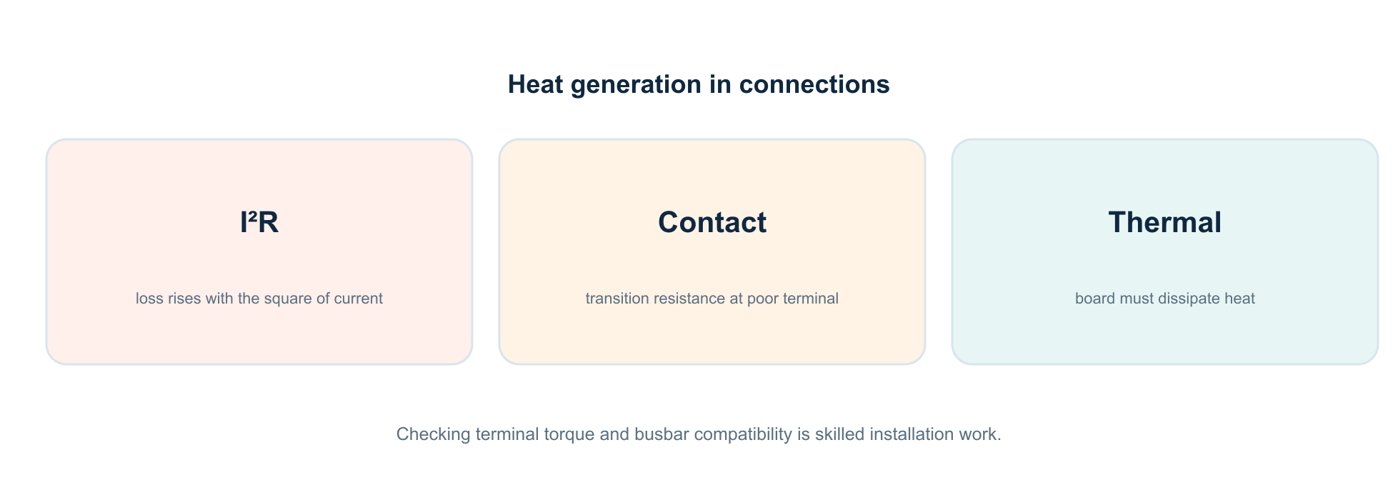
Why contact resistance matters
Power loss in a connection is approximately P = I²R. If current doubles, power loss at the same resistance quadruples. A poor terminal can heat intensely in one spot while total circuit current remains below 16 A.
Thermal loading of the board
Modular equipment also produces heat. In a crowded enclosure, device rated currents, diversity, permitted enclosure temperature, positioning, ventilation and manufacturer derating all matter. Additional contactors, smart meters and PV feeds alter the thermal balance.
Warning signs you must not ignore
Discolouration, crackling, a melting smell, browned insulation, deformed plastic, repeated thermal tripping or an unexpectedly warm cover are alarm signals. The answer is not ‘tighten it while live’, but to have the installation examined.
⚠️ If there is smoke or fire: get yourself to safety, call 112 if there is a fire risk and do not use water on live equipment. Operate a switch only if it is safe to do so.
19. Surge protection: what does an SPD do?
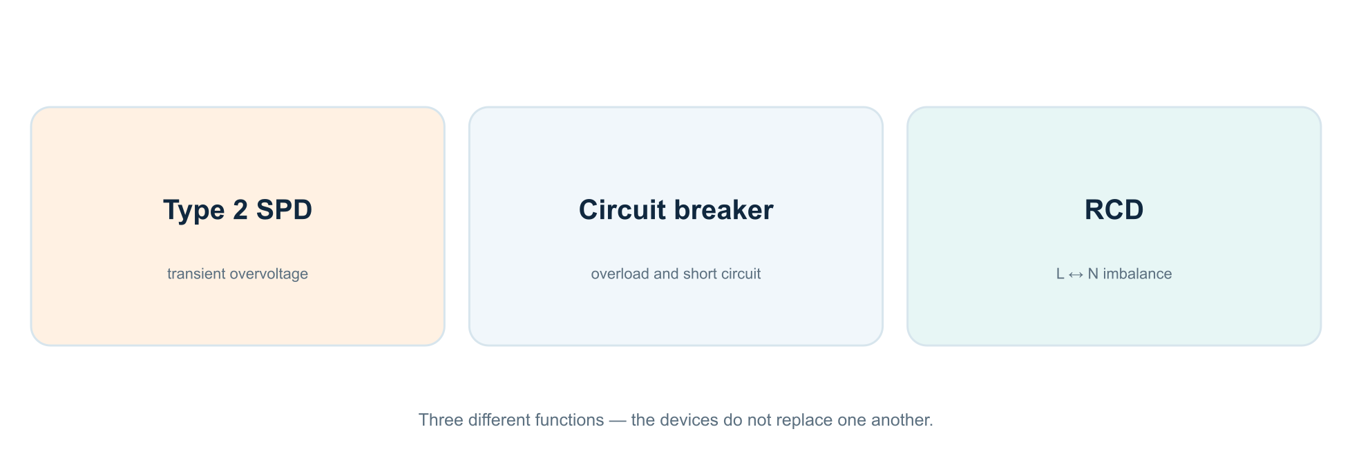
An SPD (surge protective device) protects against certain brief voltage surges, but does not replace an RCBO.
Transient overvoltage
Voltage surges can arise from lightning effects or switching operations. During such an event, a suitable surge arrester diverts part of the energy along the intended protective path. It does not automatically make a direct lightning strike harmless.
Types 1, 2 and 3
Type 1 is designed for heavier impulse applications in an appropriate lightning-protection context; type 2 is used at distribution boards; type 3 supplements protection closer to sensitive equipment. Selection depends on exposure, earthing system, installation design and coordination.
Legal nuance
The rules on surge protection do not fall one-to-one under the safety part of NEN 1010 designated through the Bbl in every situation. Determine the standard edition, applicable provisions and risk assessment separately.
PV and data cables
PV installations and outside cable routes may create additional requirements. Not only supply wiring but also communication lines and bonding can matter for effective protection.
20. PV connections: why current can also flow back
Solar panels can turn a distribution board with one energy source into an assembly with multiple possible supply paths.
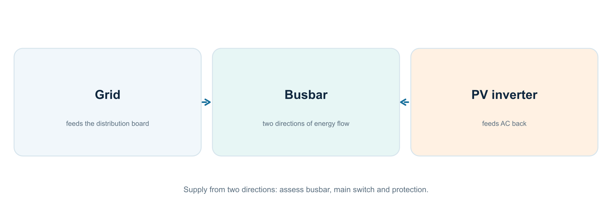
The AC side of an inverter
A grid-connected inverter supplies alternating current to a circuit suitable for it. Both inverter protection and the distribution assembly must match its type and power. Microinverters have a different DC architecture from a central string inverter, but their AC feed-in is still electrically significant.
Grid current plus generation current
A 3×25 A grid connection does not guarantee that every part of the board can see only 25 A. Generation sends power in other directions; currents in individual busbar sections depend on actual feed positions and loads. The board must be designed for that situation.
Residual-current protection for PV
A PV inverter may have capacitive leakage currents, DC components and internal detection functions. The right RCD is not automatically ‘always type B’ or ‘always type A’: the system architecture and manufacturer instructions determine the choice within installation rules.
Switching off at negative tariffs
A contactor used to disconnect PV is a separate functional layer. It never replaces mandatory electrical protection, and frequent unintended switching may create additional requirements for the switching device.
⚠️ Backfeed: a grid connection declared de-energised does not necessarily mean that all DC, battery or UPS parts are de-energised. Grid-connected inverters have anti-islanding protection, but always assess the complete installation configuration.
21. Loading a 3×25 A home in practice
A three-phase connection offers capacity, not unlimited simultaneous power. Loads and generation must be evaluated phase by phase.
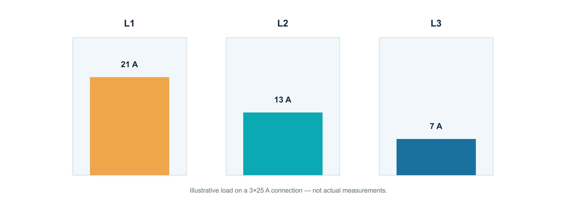
Calculation example
Suppose an oven (10 A) and heat pump (11 A) run on L1: about 21 A. L2 carries 13 A and L3 7 A. The distribution is uneven, but not immediately wrong. Another 8 A load on L1 can exceed the main protective device’s limit while the other phases still have ample headroom.
Power is not the same as loading on each phase
A home battery, PV and EV charger can reduce or alter net grid current. A P1 meter often provides useful phase readings, but a grid-exchange measurement does not automatically show actual current in every downstream circuit or busbar section.
What can be automated?
An EV charger with suitable dynamic load balancing can reduce charging current as available headroom on a phase falls. Home Assistant can reveal trends and defer non-critical appliances. Critical protection, however, must operate autonomously and must never depend on Wi-Fi or a Python script.
22. EV charger, induction hob, water heater and heat pump
Heavy loads require a different assessment from an ordinary socket for a lamp.
Each device has its own profile
An induction hob may be distributed across one, two or three phases depending on its design. A heat pump often has start-up, defrost and auxiliary-heating peaks. A water heater is usually a relatively sustained resistive load. An EV charger may carry high current for many consecutive hours.
Continuous loading matters
With sustained current, thermal limits of connections, cables and components become important. Diversity and phase allocation are part of the load calculation. DC fault-current monitoring can also matter in EV charging.
A ‘Perilex’ connector tells you too little
The presence of a five-pole outlet does not tell you which voltage, phase configuration or protection lies behind it. Wire colours and terminal assignments must not be guessed.
Design before purchase
Establish the required connection rating, load characteristic, manufacturer requirements, phase configuration and future extensions before altering the board. Being able to connect a device does not automatically mean it is safely or selectively protected.
23. Relays, contactors and smart switching
Electrical protection and functional switching are often confused online, especially when using a Shelly or another smart relay.
Different roles
A relay or contactor switches a load on command. Its contacts have a specified utilisation category, rated operating current, making capacity, electrical life and sometimes upstream-protection requirements. A circuit breaker or RCD instead has a protective function.
NO, NC and coils
NO means a normally open contact; NC means normally closed. ‘Normal’ means the coil is not energised. On power failure, this choice partly determines what happens to the appliance. A smart relay driving a contactor coil is a control circuit, not a safety chain by itself.
Snubbers and inductive loads
Switching off a coil can produce a voltage spike. RC snubbers, varistors or other devices may limit it, but selection depends on coil type, voltage and manufacturer instructions.
The correct fail-safe response
If Home Assistant, Wi-Fi or the Shelly fails, the system must remain predictable. For PV switching, protection must be independent of automation, and restoration behaviour must be designed and checked.
24. Smart metering: P1, CT clamp or direct energy meter?
Energy management becomes reliable only when it is clear which part of the installation a meter observes.
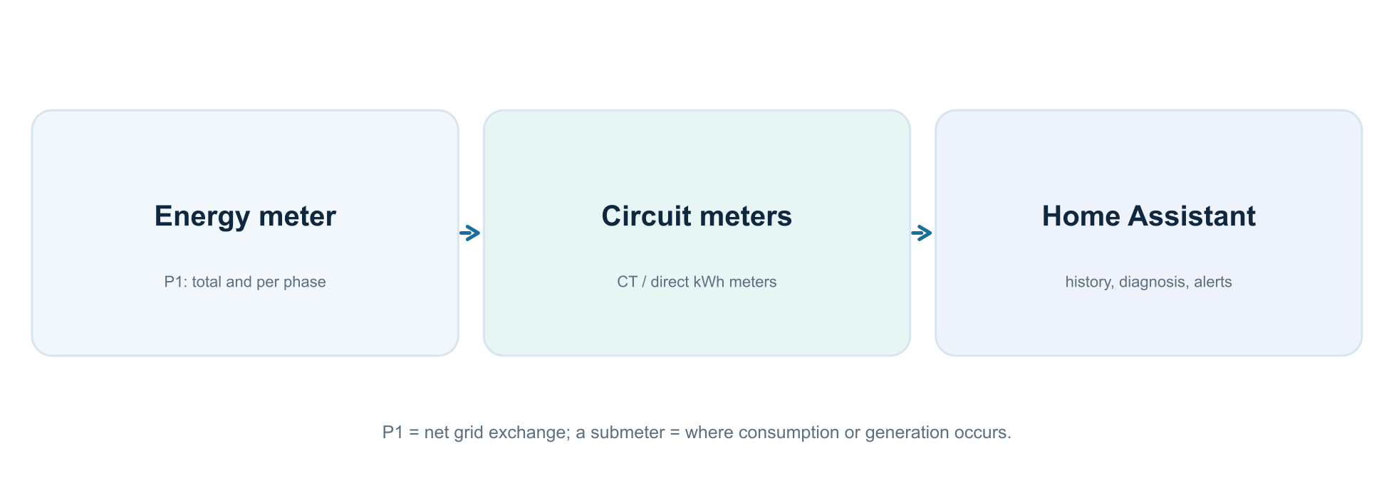
P1: the grid connection as measurement boundary
A smart meter records import and export at the grid connection, often with values per phase. It does not by itself tell you whether consumption comes from the living room, kitchen or heat pump.
CT clamp: measuring without a series current path
A current transformer measures the magnetic field around a conductor. Correct measurement requires surrounding the right active conductor and using a suitable voltage reference and phase assignment in the meter. If phase and neutral pass through one CT together, their fields largely cancel in normal operation.
Direct DIN-rail meter
A direct kWh meter carries the measured current through its own measurement path and may be more accurate at light loads than certain CT solutions. Rated current, accuracy class, installation requirements and communication method vary by device.
More channels are not automatically better
A three-phase meter is not necessarily designed to measure three arbitrary single-phase circuits on different phases. Check the product documentation, measurement threshold, direction and separate energy accumulation.
25. Home Assistant: useful sensors and dashboards
A dashboard is not electrical protection. Its main value is spotting fault patterns, unusual loading and grid-voltage problems early.
Useful measurements
-
Grid voltage on L1, L2 and L3; current per phase and actual grid exchange if available.
-
Present power and cumulative kWh from PV and major loads.
-
Measurements for separate circuits, clearly named and checked for double counting.
-
Meaningful events: frequent trips, sustained peak loading, unexpected overnight consumption and loss of measurement communication.
Energy dashboard and measurement meaning
For long-term energy statistics, Home Assistant expects stable cumulative energy entities with the appropriate unit, device_class and state_class. An instantaneous watt value cannot be treated directly as a total in kWh without proper integration over time.
Be restrained with automation
Only make advisory or comfort-oriented actions depend on HA. Examples are alerts, water-heater scheduling or reducing EV charging power through a suitable charger controller. Protection against short circuits, electric shock and fire always remains hardware-based.
⚠️ System principle: the electrical installation must remain safe on its own without a network, software or cloud connection.
26. Working de-energised: a professional procedure
An off main switch, loose wire or extinguished LED is not reliable proof that a board is safe to touch.
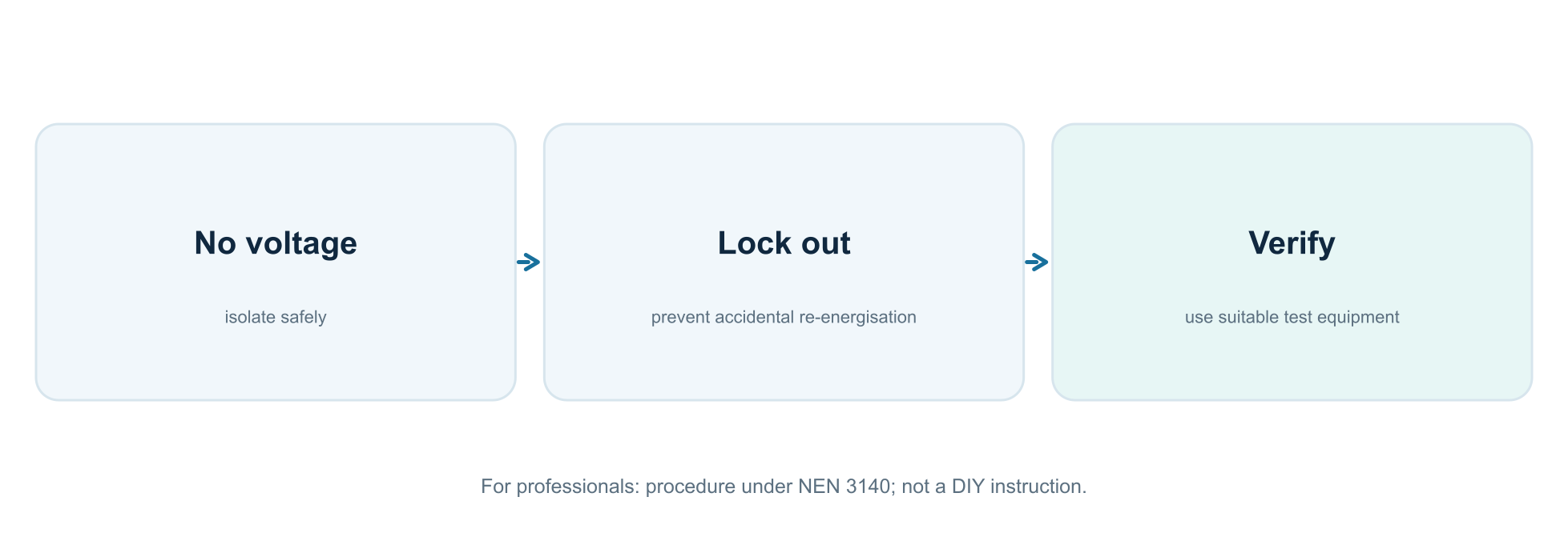
Risks before work
Risk assessment covers all possible supplies, including solar generation, batteries, UPS systems, emergency supplies and backfeeds. A broken neutral or inaccurate documentation can increase the danger further.
Main elements of safe work
The safety approach behind NEN 3140 includes correct isolation, prevention of re-energisation, verification of absence of voltage, dealing with nearby live parts and suitable personal protective equipment. The competent worker determines the precise actions and sequence from the actual installation.
Which measurements are involved?
Checking absence of voltage requires suitable, verified test equipment and a method that excludes falsely reading zero. Testing an open distribution assembly brings its own arc-flash and touch hazards; an ordinary inexpensive multimeter is not permission to work.
⚠️ DIY boundary: do not remove covers or seals, loosen busbar connections or carry out live measurements based on this article. Operate only components intended for users.
27. What does an installer check after an extension?
An installation is not safe merely because it happens to work when switched on. Verification assesses both design and completed work.
Inspection before commissioning
An installer visually assesses product suitability, connections, labels, isolation, bonding, protective measures and finishing, among other things. Correct construction of the complete board is part of that assessment.
Electrical tests
Depending on the installation and applicable requirements, handover includes measurements and checks such as protective-conductor continuity, insulation resistance, polarity, fault-loop impedance, RCD operation, phase sequence, functional testing and verification of disconnection conditions.
Documentation
A useful circuit schedule says more than ‘kitchen’: ideally it also records the phase, protection type, rating, special loads and relevant energy sources. The details must be updated after an extension.
Reinspection
A formal inspection is different from pressing a test button periodically. Availability and safe operation change with use, modifications, moisture, wear and ageing.
28. Why does a circuit breaker or RCD keep tripping?
Not every trip has the same cause. The front of the tripped device may sometimes show which protective principle likely operated.
Circuit breaker tripped
Possible causes include overload, inrush current, a short circuit or a faulty appliance. If it trips immediately again after being reset, do not force it and do not keep repeating the attempt: the underlying fault may be serious.
RCD tripped
Possible causes include insulation faults, moisture, defective appliances, cumulative leakage, incorrectly shared neutrals or an unsuitable device choice. An RCD that trips when one circuit is switched on gives a clue but does not fully prove the fault location.
Main protection tripped
Sustained overload on one phase, a severe fault or selectivity issues may be responsible. Main protection is generally not an accessible fuse for a resident to replace.
Special warnings
A burning smell, water ingress, humming or crackling, visible discolouration or recurring faults after repair require expert inspection. A defective neutral or earthing fault can be dangerous without a circuit ‘tripping neatly’.
29. Modernising your distribution board: a sensible plan
A modern board is not necessarily better because it has more breakers. Safe renovation starts with the whole home electrical installation.
Step 1: inventory
Record main protection, phase count, existing circuits, PV capacity, hot and sustained loads, earthing, existing wiring and future additions. Distinguish measured values from assumptions.
Step 2: design and component choice
Decide whether a completely new distribution assembly is more sensible than adding components incrementally. Reserve thermal and physical space and choose a demonstrably compatible manufacturer or distribution system. Consider accessibility and what happens during faults.
Step 3: installation and verification
An authorised installer mounts, connects and verifies the installation to the applicable requirements. Existing parts affected by the changes are also examined. Ask for relevant handover information and an updated circuit schedule.
Step 4: monitoring is supplementary
P1 and circuit-level measurements can then be added so phase loading, PV and appliances become measurable. Home Assistant completes the insight loop but does not perform the primary protective function.
30. Example: a 3×25 A home with solar panels and heat pump
This is a fictional case based on a common fully electrified three-phase home with solar panels.
Situation
The home has a 3×25 A connection, an induction hob, heat pump, water heater and PV inverters. Energy monitoring and future EV charging are wanted. It seems logical to add ‘a few more circuits’, but several design questions arise.
First, inventory
Which appliances are single- or three-phase? Which circuits carry sustained loads? How is PV fed in, and which busbar segments may carry grid and generation current simultaneously? Which RCD types do the manufacturers specify? Are neutral and PE demonstrably correct?
Then, risk-based design
The installer assesses maximum and likely simultaneous demand, fault currents, cables, thermal component loading and outage scenarios. EV charging uses an appropriate charging controller with local, autonomous load balancing. PV protection remains separate from an optional contactor for dynamic tariffs.
Finally, insight
P1 provides the net balance with the grid. Separate energy meters on the heat pump, water heater and EV help explain actual consumption and phase patterns. This reveals which optimisations are economically worthwhile without altering electrical protection.
31. Ten persistent misconceptions about distribution boards
Many errors arise when one number on a component is treated as an explanation of the whole installation.
-
‘A 40 A main switch trips at 41 A.’ No: it is primarily a switching and isolating component.
-
‘A 30 mA RCD prevents every electric shock.’ No: it detects only the types and patterns of residual current for which it was designed.
-
‘A C16 is safer because it trips less readily.’ Not without assessing fault current and loop impedance.
-
‘A 3×25 A connection provides 75 A everywhere.’ No: each of the three phases has its own limit.
-
‘Blue is always safe.’ Neutral normally carries current and can have dangerous voltage during faults.
-
‘PE may be used as a return conductor.’ No: the protective conductor has a safety function.
-
‘Every comb busbar fits every breaker.’ No: component compatibility must be demonstrated.
-
‘With the main switch off, everything is safe.’ Not proven; other supplies may exist.
-
‘Solar panels do not affect the board.’ They do: current direction and busbar loading can change.
-
‘Home Assistant can replace protection.’ No: software is only supplementary.
32. Points to discuss with your installer
Use this list to make a technical conversation efficient. It is not a checklist allowing a layperson to commission an installation.
Record beforehand
-
The connection type, main protection and earthing system have been identified.
-
There is an up-to-date circuit diagram, including phase allocation and special supplies.
-
Existing and planned loads, PV, battery, EV and heat pump have been listed.
-
The applicable NEN edition, Bbl reference and manufacturer documentation have been established.
Design questions
-
Are RCD types, disconnection conditions and fault-current levels substantiated?
-
Is the entire distribution assembly suitable under the applicable product standard?
-
Have the busbar, thermal load, cables, terminals and feed-in positions been assessed?
-
Are the correct isolators accessible and are multiple supplies clearly labelled?
After handover
-
Have measurements and verification been documented, including deviations and remedial actions?
-
Has the circuit schedule been updated and have user-accessible controls been explained?
-
Are digital monitoring functions separated from primary electrical protection?
⚠️ Final advice: establish technical safety and standards compliance first; only then extend components and add smart automation.
33. Glossary for the distribution board
A compact reference for common technical abbreviations.
ALS / RCD: residual-current device; detects residual current. RCBO: combined RCD and overcurrent protective device. MCB: miniature circuit breaker. SPD: surge protective device. N: neutral conductor; normal return current. PE: protective conductor. PEN: combined protective and neutral conductor in specific network configurations.
In: rated current. IΔn: rated residual operating current of an RCD. Icn / Icu: stated short-circuit breaking-capacity values, depending on product standard. Zs: fault-loop impedance. kA: kiloampere, one thousand amperes. kWh: amount of energy. kW: instantaneous power. cos φ / power factor: ratio of active to apparent power under sinusoidal conditions; for non-linear loads, overall power factor is broader.
Selectivity: only the intended downstream protective device trips within specified fault ranges. Earthing system: for example TT or TN, describing how supply earthing and protective conductors are arranged. DIN rail: mechanical mounting rail. Busbar: current-distribution rail. Anti-islanding: inverter function that prevents unintentional island operation when the grid is lost.
One more important rule
Recognising a technical term is not the same as being sufficiently competent to work with it. Electrical safety relies on coherent design, correct implementation and independent verification.
34. Sources, standards status and editorial responsibility
This article was written independently and refers to official NEN publications, legislative information and specialist standards commentary. Standards are copyrighted; this guide does not replace their original texts.
Primary sources
-
NEN 1010:2020+C1:2024 — NEN, current main publication for low-voltage electrical installations.
-
NEN 1010-8:2026 — NEN, additional functional aspects of low-voltage installations.
-
NEN 3140:2011+A3:2019 — NEN, safe operation of low-voltage systems; NEN 3140:2026 Ontw. is a draft edition.
-
NEN-EN-IEC 61439-3:2024 — distribution boards intended for operation by ordinary persons.
-
Besluit bouwwerken leefomgeving and Omgevingsregeling, Annex II — the legally designated edition and application limits are decisive.
Explanation and standards status
-
NEN news item ‘Vijf veelgebruikte Bbl-normen nu vrij toegankelijk’ (21 September 2026): publication and legal designation are different things.
-
Nieuws1010, March 2026: specialist analysis of the NEN 1010 edition designated at that time; interpretations within the sector differ.
Publication and liability
The explanation is informative. Illustrations are conceptual and are not suitable for physical installation. Standards compliance, device selection, cable calculation, protection coordination, inspection and implementation remain specific to the installation and project and require competent personnel. This article may contain errors and does not authorise installation work. Have changes to the distribution board assessed before work and verified afterwards.