
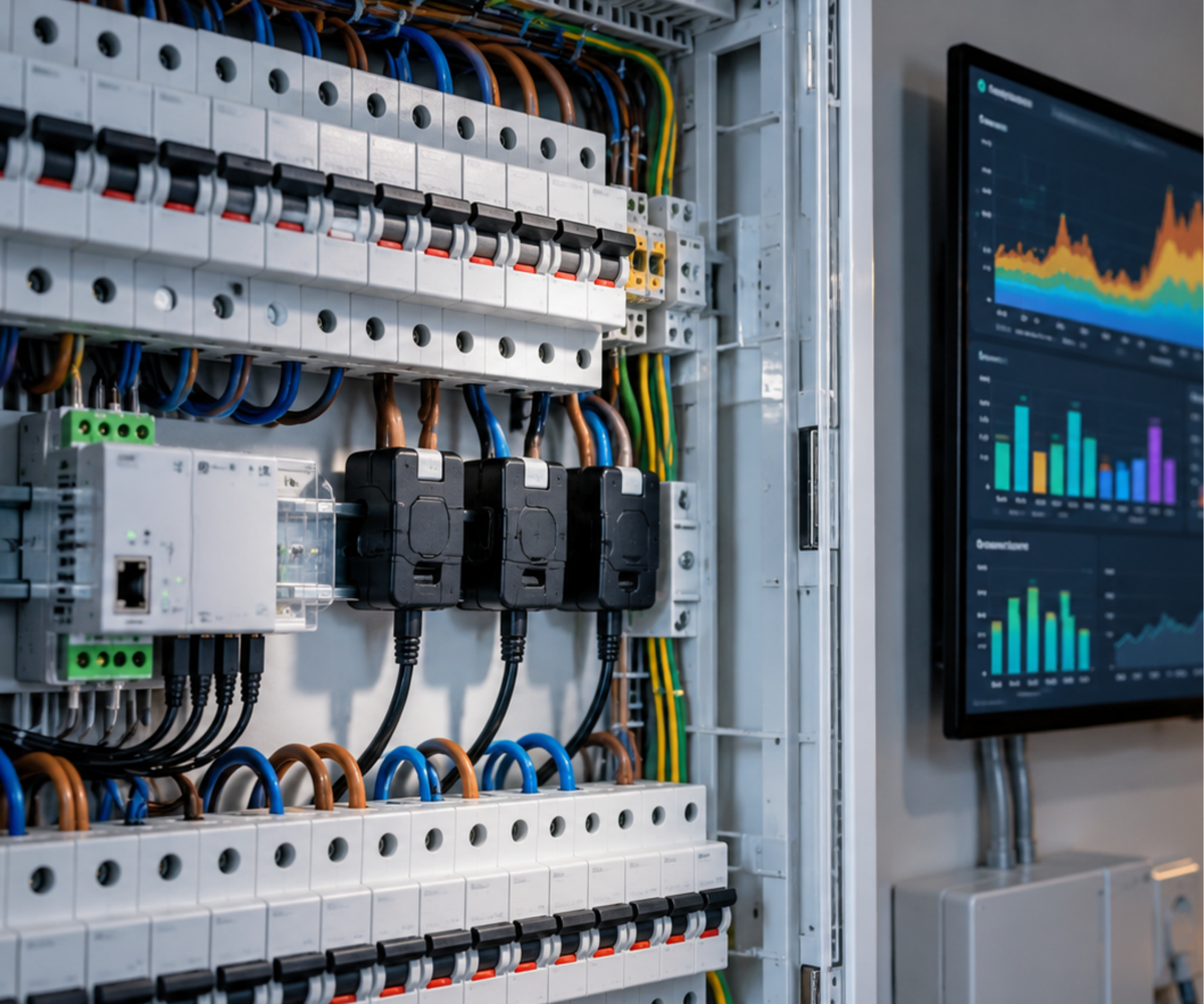
CT clamps, DIN rail and Home Assistant. From Shelly Pro EM and Pro 3EM to HomeWizard, Modbus and multi-CT systems, with safe conceptual diagrams, measurement examples, configuration and a practical selection guide.
01. From smart plug to final circuit
Not every appliance deserves its own smart plug. Sometimes the electrical circuit itself is the most useful measurement point.
The central question
You measure heavy appliances individually, but small consumers—from routers to lighting—are scattered across several sockets. How can you gain insight without buying and managing dozens of plugs?
The short answer
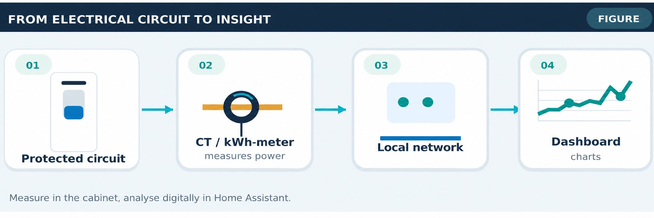
Measure each electrical final circuit. A current transformer (CT) around the correct outgoing live conductor, or a suitable kWh meter installed in series with that circuit, can report its consumption. Home Assistant turns those measurements into charts, historical statistics and notifications.
What this does and does not reveal
- It does reveal a circuit’s total load, daily consumption and unexpected changes.
- It does not identify exactly which appliance on the same circuit used the energy. That requires separate measurement or an indicative power profile.
- Three CT channels do not automatically mean three arbitrary circuits: voltage references and phase assignment must be correct.
How to read this guide
We begin with measurement principles, compare six device families, discuss safe installation concepts, and finish with integration, YAML, practical cases and a selection guide.
Caution: Start with two or three relevant final circuits and expand only after confirming that the readings are reliable.
02. Watts, watt-hours and power factor
Power is often confused with energy. A trustworthy dashboard requires a clear distinction.
Power (W) is a snapshot
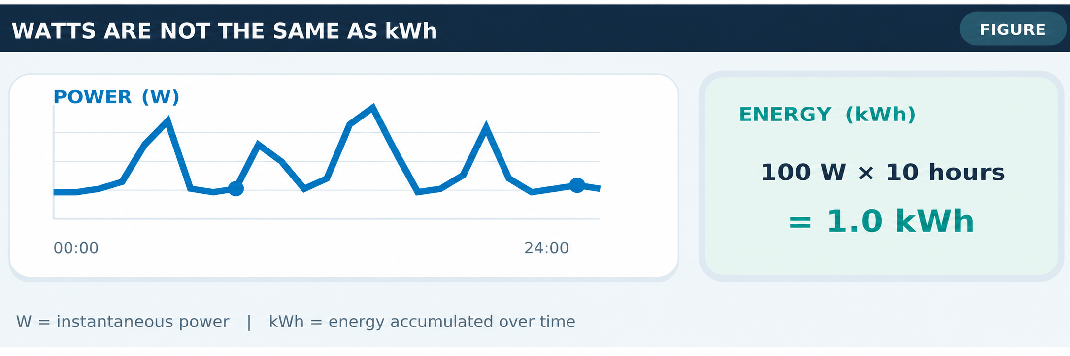
A sensor reporting 85 W indicates how much active power a circuit is drawing at that moment. The number may change every second. A 2,000 W kettle running for six minutes uses approximately 0.20 kWh.
Energy (kWh) is the total over time
Energy is power integrated over time: 100 W for 10 hours equals 1 kWh. Use kWh—not a single W reading—for costs and monthly comparisons.
Why 230 V × A is not always enough
A CT measures current. Actual active power also depends on voltage, phase shift and waveform. A load drawing 1 A at 230 V with a power factor of 0.60 uses approximately 138 W of active power, not 230 W.
Three practical readings
- W: immediately useful for detecting on/off states and peaks.
- kWh: suitable for trends, costs and the Energy dashboard.
- A, V and power factor: useful for diagnosis and checking the measurement.
Pay attention to the measurement threshold
In a house full of power supplies, adapters and standby devices, the specification at low current may matter more than the quoted accuracy class at high load.
Caution: A device measuring only current, or assuming a fixed voltage, provides at most an estimate of real energy use.
03. Why a P1 meter is not enough
A P1 reader is an excellent starting point, but records the home as a whole.
Three levels of measurement
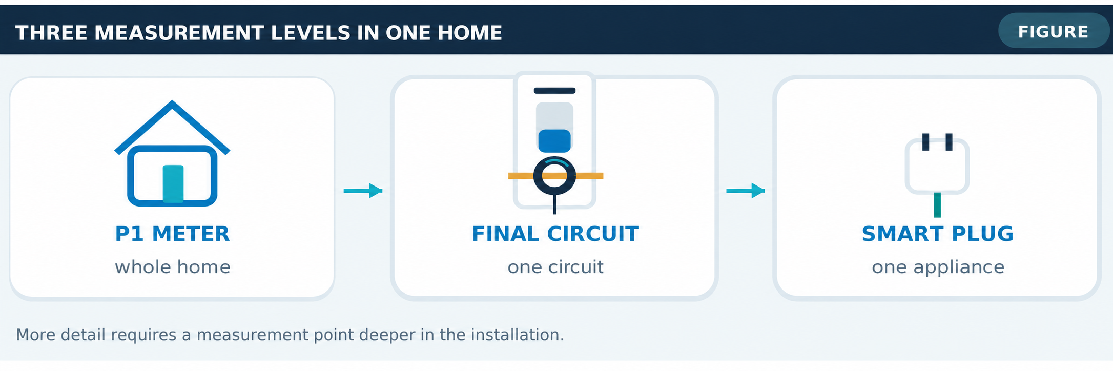
- Main meter/P1: grid import and export. With solar panels, the smart meter sees the net result of simultaneous production and consumption.
- Final-circuit meter: one downstream circuit, such as the living room, office or kitchen.
- Appliance meter: one specific appliance, such as a washing machine or server.
What is missing if you have only P1?
If the meter shows 400 W of grid import while the solar panels produce 1,000 W, the home is consuming roughly 1,400 W at that moment, provided there are no other energy flows. You still do not know which circuit is responsible.
One source, different perspectives
A CT on a final circuit can show whether an unexpected 300 W comes from the living room or the office. A smart plug on the television can break down that load further.
Avoid double counting
If you add both a circuit meter and a plug measuring an appliance on that same circuit to the Energy dashboard, set their hierarchy correctly. Home Assistant supports upstream-device relationships for nested meters [9].
Caution: P1, final-circuit and appliance measurements complement one another; they are not three additional sources of electricity.
04. How a CT clamp works
A CT clamp measures alternating current indirectly. The load does not pass through the smart meter’s electronics.
The principle
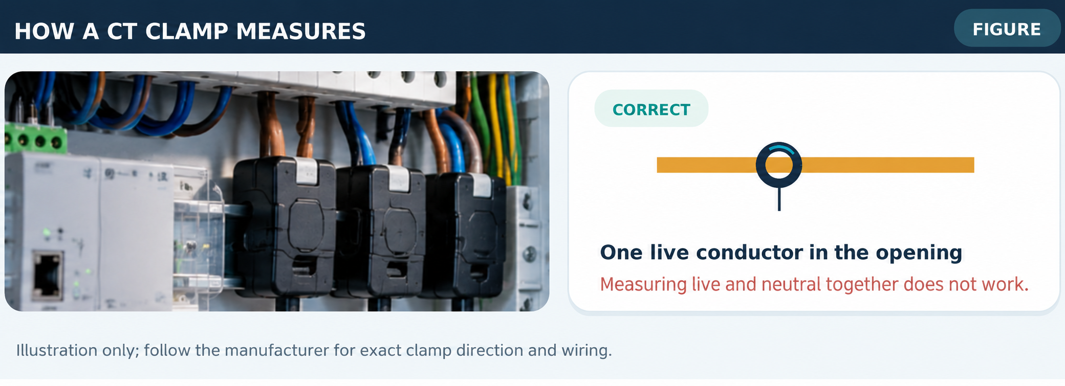
A closed measuring core surrounds one conductor. Alternating current produces a magnetic field, which creates a proportional measurement signal on the secondary side. The meter combines that signal with a voltage reference to calculate power.
The crucial location
To measure a single-phase circuit, fit the CT around one individual current-carrying conductor of that circuit. If you clamp live and neutral together, their magnetic fields largely cancel during normal operation.
Direction matters
CTs often have an arrow or K/L marking. Reversing a clamp may make the displayed power direction negative. That is not necessarily an error: a solar circuit may actually export power.
Safety and compatibility
- Use only CTs and cables approved by the manufacturer.
- Do not move or disconnect CTs while energised if the manufacturer forbids it; an open secondary circuit can be dangerous.
- A CT is not a circuit breaker, residual-current device or isolator.
- Have installation and interpretation handled by a competent electrician.
Caution: The figure illustrates a principle; it explicitly does not replace the product-specific wiring diagram.
05. One phase, three circuits
Multiple measurement channels can be used efficiently side by side for single-phase final circuits that share the same phase.
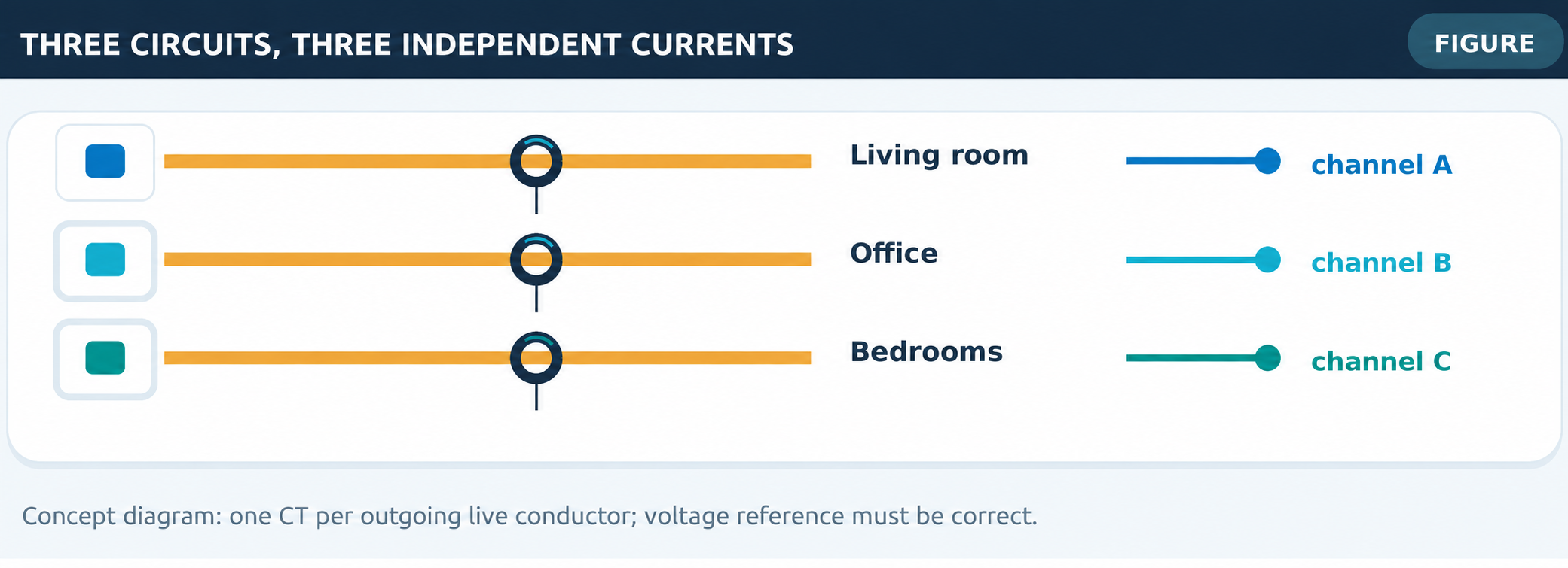
Example: three independent final circuits
Circuit 4 supplies the living room, circuit 7 the office and circuit 9 the bedrooms. Each channel measures only its own outgoing current. The existing circuit breakers continue to protect and switch these circuits.
One meter, three channels
The Shelly Pro 3EM supports a single-phase connection concept [1]. It can therefore measure three separate currents on one phase, provided the voltage references, clamps, settings and product wiring diagram match the actual installation.
Two-channel option
The Shelly Pro EM-50 offers two CT inputs with a single-phase voltage reference and DIN-rail mounting [2]. That is often enough for an initial trial with the living room and office.
An electrical circuit remains an electrical circuit
Different appliances on the same final circuit remain grouped in one measurement. Physically placing three outgoing conductors from different circuit breakers inside one CT is not the intended measurement principle. Software can sum several circuit readings instead.
Plan the installation
Allow space for the power supply, CT leads, separation of high- and low-voltage wiring as specified by the manufacturer, and access to the meter.
Caution: Ask the installer to establish beforehand whether all selected circuits really share the same phase.
06. Three phases: phase or final circuit?
A three-phase energy meter does not automatically provide the same measurement as a system monitoring three final circuits.
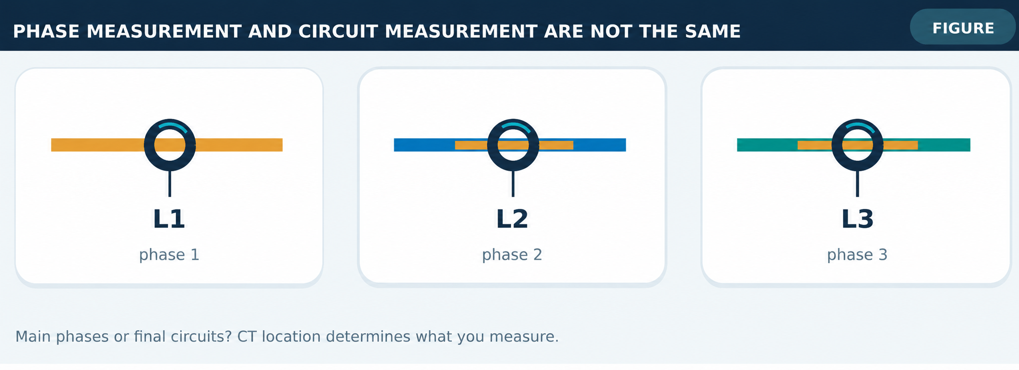
Three key questions
- Do you want to view the whole home by phase? Measure the three relevant phase conductors in the main distribution.
- Do you want to view three separate circuits? Measure the outgoing conductors of those circuits, using the correct phase-dependent voltage references.
- Do you want to measure one three-phase load? Then the three channels together belong to, for example, an EV charger or three-phase circuit.
Phase assignment is essential
Combining a current channel on L2 with an L1 voltage reference can produce incorrect power readings. Check A/B/C channel assignment, phase sequence and configuration against the manufacturer’s instructions.
Separate protection devices
Do not join neutral conductors from different RCD-protected final circuits. A smart energy meter must not bypass existing protective measures.
Solar generation and export
Power flow can reverse on a circuit with generation. Record import and export separately on bidirectional meters and choose the correct sensors in Home Assistant.
Practical advice
First draw the actual distribution. It determines whether a Pro 3EM, several two-channel meters or individual kWh meters make sense.
Caution: On a three-phase connection, the same meter configuration can answer very different questions.
07. Which meter fits which question?
There is no universally best meter. Channel count, measurement method and low-load threshold determine the choice.
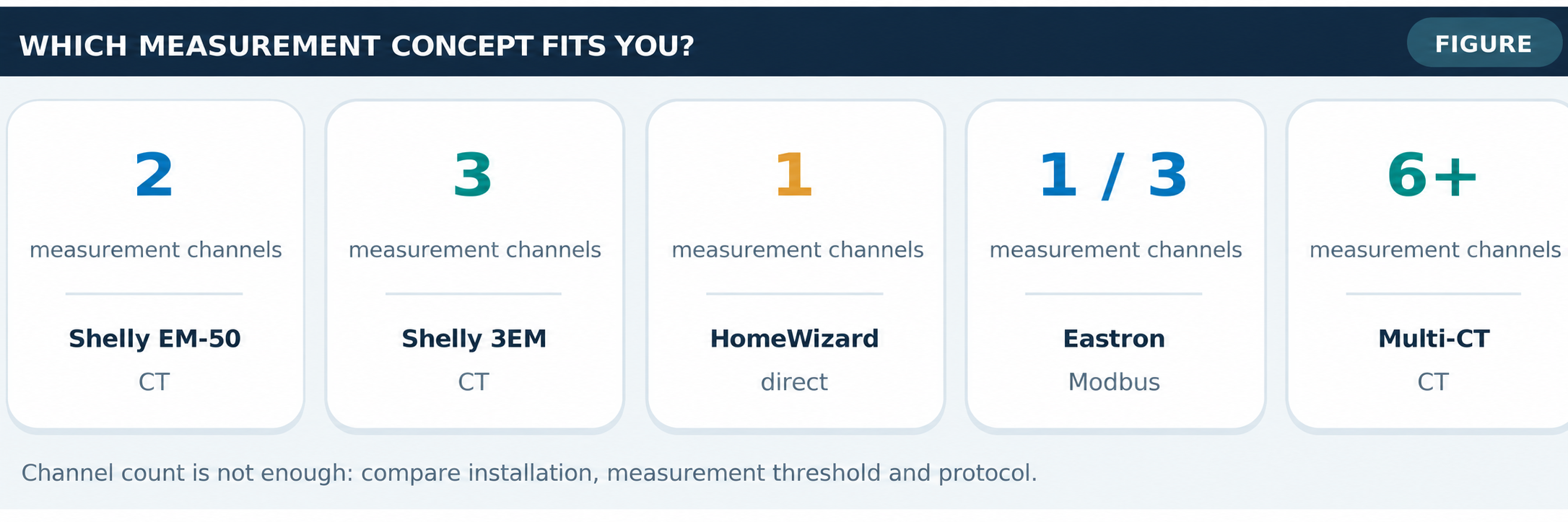
Quick comparison
- Shelly Pro EM-50: two single-phase CT channels, Ethernet/Wi-Fi and DIN rail. Compact monitoring of two circuits [2].
- Shelly Pro 3EM: three CT channels, single- or three-phase configuration, Ethernet/Wi-Fi and DIN rail. For multiple circuits or phases [1].
- Shelly EM Gen3: two single-phase CT channels, Wi-Fi and a compact built-in form. For particular retrofit applications [3].
- HomeWizard Wi-Fi kWh Meter: single- or three-phase versions, direct in-series installation and local API; one circuit per meter [4].
- Eastron SDM120/SDM630: DIN-rail meters with Modbus options. Interesting for a larger wired RS485 architecture [5].
- OpenEnergyMonitor emonPi/emonTx: multiple CT inputs and flexible voltage measurement; requires more integration work [6].
Two decisions that matter
If you need only two or three channels, a ready-to-use local Shelly often wins on convenience. For ten or more circuits—or if you deliberately want to write your own software—a multi-CT system deserves attention.
What about small standby loads?
Do not look only at percentage accuracy. In particular, find out the minimum load at which energy is actually recorded.
Caution: Always check the firmware version, CT type, availability and specifications of the exact model before purchase.
08. Shelly Pro EM-50
For two final circuits, this is the most straightforward Shelly option.
What the device offers
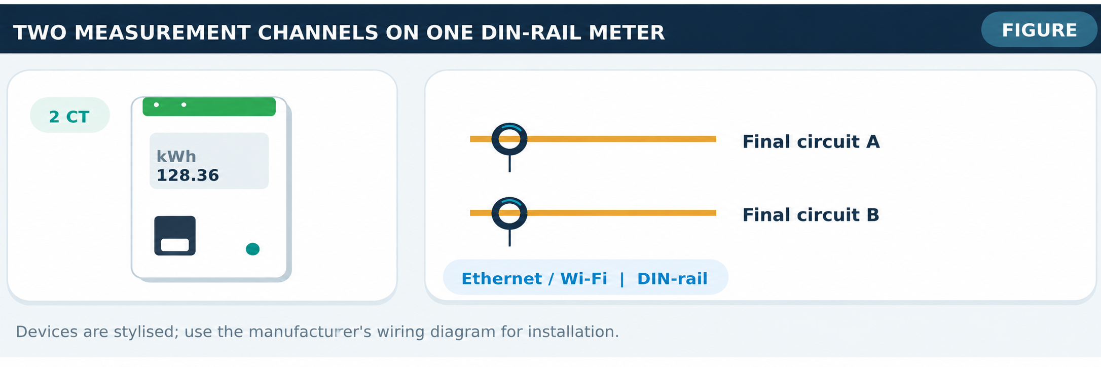
The Shelly Pro EM-50 is a two-channel single-phase DIN-rail energy meter. It has two CT inputs, a local web interface, Ethernet and Wi-Fi. The manufacturer quotes 50 A as the current-input measuring range and storage of about 60 days of minute-by-minute data [2].
Practical example
Channel A measures living room and multimedia; channel B measures the office. In Home Assistant, use W for current load and kWh for daily and monthly consumption. The existing circuit breakers continue to protect the actual final circuits.
Benefits
- Two circuits with one meter and one network connection.
- Ethernet is often more reliable inside a metal distribution cabinet.
- Local availability without a mandatory cloud account.
- Measurement can be used independently of any switching automation.
Points to consider
The device has a small relay contact for contactor control; it is not a direct heavy-duty circuit switch. Do not use it instead of a circuit breaker or RCD. Also verify that the chosen circuits can electrically be measured with the same voltage reference.
My assessment
A sensible first choice for two useful circuits such as a living room and office, provided low-load performance meets the need.
Caution: Prefer using only the measurement function for final-circuit monitoring; do not introduce an unintended switching dependency.
09. Shelly Pro 3EM
Three channels and strong local integration make this meter versatile, but it has important limits.
What is it suitable for?
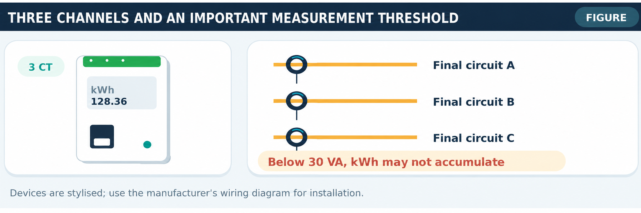
The Pro 3EM measures voltage, current, active and apparent power, and cumulative energy per phase or channel. The manufacturer supports both three-phase and single-phase configurations [1].
A useful distinction
With CT-A on L1, CT-B on L2 and CT-C on L3 of the main supply, you measure the home’s three phases. With the CTs on three specific outgoing conductors, a suitable single-phase arrangement can monitor three final circuits. The measurement setup changes even though the device is the same.
Low load: the trap
The documentation states a 30 VA per-channel threshold for energy accumulation at very low load and up to approximately ±5% current-measurement error below 1 A [1]. A continuously powered 8 W device may therefore not be fully recorded as kWh. Always check the exact firmware and device settings.
Example
The living room, kitchen sockets and office become separately visible during the day. Power peaks may suggest appliances, but cannot identify an individual appliance with certainty.
My assessment
Strong for medium and high loads and phase monitoring. It would not be my first choice if the main goal is to count only standby consumption of a few tens of watts with precision.
Caution: An attractive real-time watt reading does not guarantee that the same small load is correctly accumulated by the kWh counter.
10. Shelly EM Gen3
A compact two-channel meter for places where a large DIN-rail meter is impractical.
What is different?
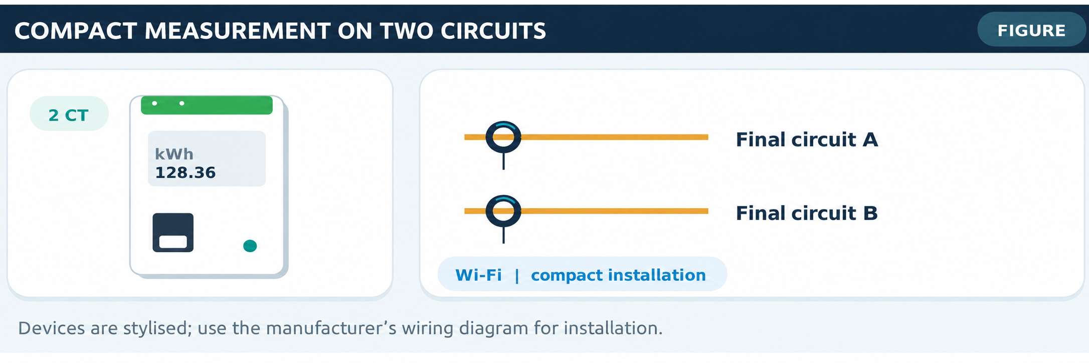
The EM Gen3 has two CT channels and communicates over Wi-Fi. This compact device is intended for installation in suitable electrical enclosures [3]. Unlike the Pro EM-50, Ethernet is not a standard connection here.
When should you choose it?
One example is a suitable distribution enclosure with little free DIN-rail space, where measuring two circuits would still be useful. Installation space, electrical shielding and manufacturer instructions still apply.
Technical limitation
EM Gen3 documentation also states a 30 VA no-load threshold per channel. The manufacturer specifies current-measurement deviations of up to ±5% in the low 0–1 A range [3]. That is a serious consideration for precise standby investigations.
Practical example
An outbuilding has two relevant circuits: general sockets and lighting. An EM Gen3 makes both visible while Home Assistant compares their separate time series.
My assessment
Useful for retrofit work and limited space. Choose the Pro EM-50 if a wired network connection and DIN-rail installation matter more; choose a suitable direct kWh meter if accurate small energy quantities are the priority.
Caution: Not every device capable of measuring current is equally good at long-term low-power measurement.
11. HomeWizard Wi-Fi kWh Meter
If you prefer direct measurement and a digital energy meter on a DIN rail, look at HomeWizard.
Measurement principle
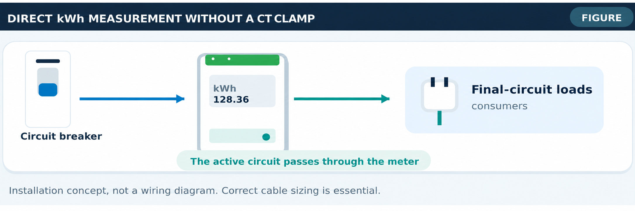
The HomeWizard kWh Meter is installed as a separate meter in the circuit concerned, so no loose CT clamp is needed. The single-phase version is suitable for one single-phase circuit and the three-phase version for one complete three-phase circuit [4].
Benefits
- Its own clearly defined measurement point for each measured circuit.
- Local API and Home Assistant integration [7].
- The manufacturer states MID classification for its kWh meters.
- Useful for a heat pump, EV charger or another clearly separate load.
Downsides
Each final circuit needs its own meter and DIN-rail space. The conductor is actually routed through the device, so installation work is normally more involved than fitting a CT clamp.
Price indication
At the time the source was compiled, the manufacturer advertised the single-phase Wi-Fi kWh Meter for €59.95 [4]. Check the current price, model differences and availability.
My assessment
For one or two important circuits, or small loads you want to quantify reliably, a suitable MID kWh meter is often more attractive than a universal CT solution.
Caution: A direct meter must never be added to an existing protected final circuit without an installation assessment.
12. Eastron SDM120 and SDM630
For a robust wired system, a network of Modbus meters is worth considering.
Two device families
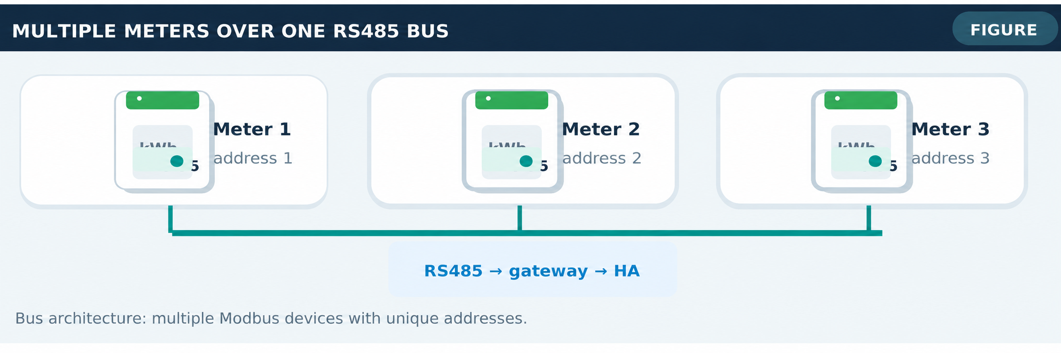
The SDM120 family targets single-phase circuits; SDM630 models are intended for three-phase connections. Both families have variants with different interfaces and certifications, so check the exact model suffix.
RS485 as the backbone
A Modbus RTU meter exchanges data over an RS485 bus. Multiple meters can be read on the same bus, each with a unique slave or unit address. Termination, cable routing and communication speed must match the manual.
Why choose it?
- Suitable for monitoring more circuits independently over time.
- Measurement itself does not depend on Wi-Fi.
- Many registers are available: kWh, W, V, A, frequency and possibly power factor.
- Integration is possible through the official Home Assistant Modbus integration [8] or a carefully maintained custom integration.
Less suitable for
Measuring two circuits quickly without technical configuration. RS485, register addresses, byte/word order and possible gateways make the entry barrier higher.
My assessment
Excellent for a larger, lasting installation. Document each meter’s model, address, register map and corresponding final circuit.
Caution: The SDM120 is not a three-channel meter. An SDM630 measures one three-phase circuit, not automatically three independent single-phase circuits.
13. OpenEnergyMonitor and ESPHome
When you want six to twelve CT measurement points, a modular system deserves serious consideration.
The OpenEnergyMonitor route
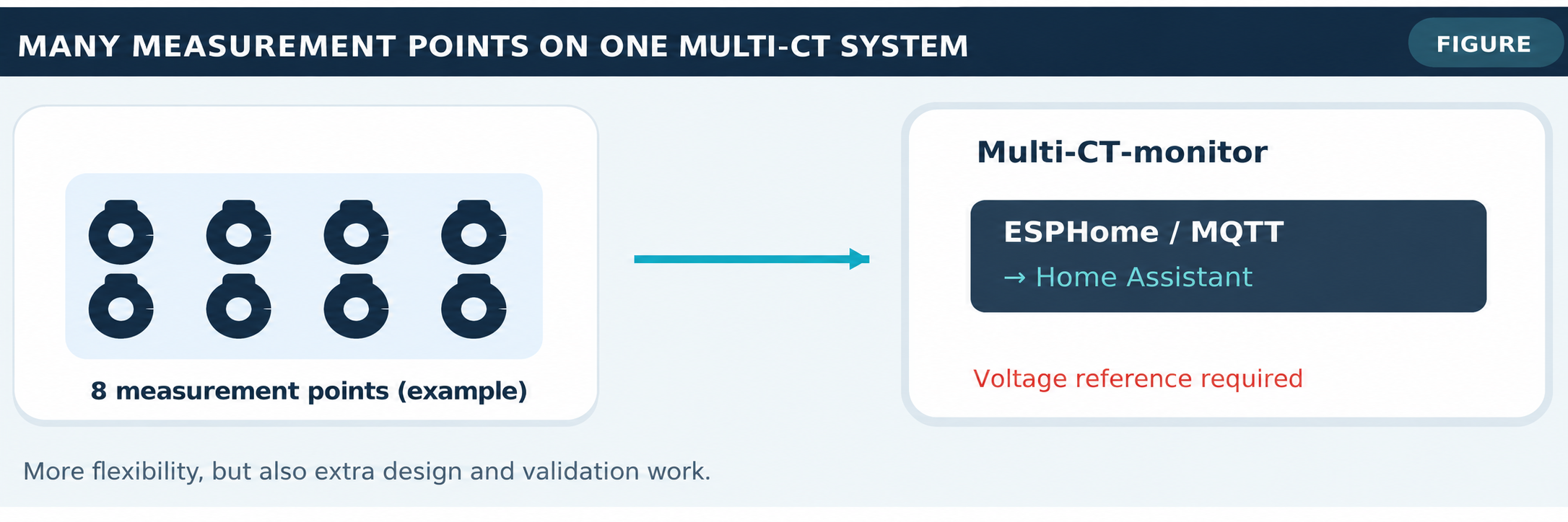
The emonPi2 has six CT inputs by default and supports expansion with suitable hardware and firmware. Newer emonTx variants also offer extensive options. Active-power measurement uses a suitable voltage sensor [6].
Connection to Home Assistant
Project documentation describes routes through MQTT, ESPHome and EmonCMS. In a Home Assistant-focused installation, suitable hardware can provide native ESPHome sensors or MQTT entities [6].
Why not simply use six ESP32 ADC inputs?
A CT produces a measurement signal that needs analogue conditioning, safe isolation and appropriate sampling. Accurate real power also requires sampling the voltage waveform. A generic ADC project assuming a constant 230 V is of limited reliability with non-linear loads.
A practical build concept
- Certified power supplies and suitable CT inputs.
- Properly calibrated voltage reference and channels.
- Local MQTT or ESPHome connection to Home Assistant.
- Logging of range, measurement threshold, calibration date and fault conditions.
My assessment
The best option for a technically capable hobbyist who needs many channels and accepts ongoing maintenance. For two circuits, the extra work is hard to justify.
Caution: Do not place unprotected DIY mains-measurement electronics inside a distribution cabinet.
14. Measuring is not the same as switching
An energy meter must not inadvertently become a point of failure for the home.
Three kinds of device
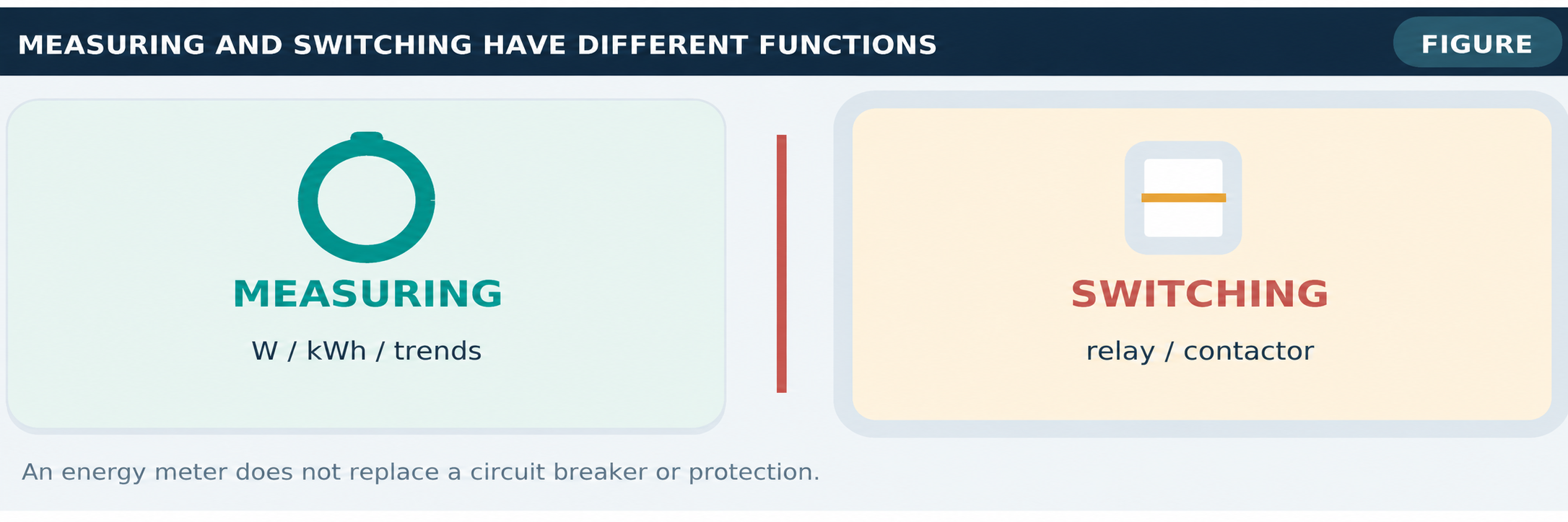
- Measurement meter: reads current, voltage and energy but does not interrupt the final circuit.
- Smart relay or switching actuator: switches a load within its specified rating.
- Contactor: electromagnetic power switch, which still needs suitable protection and control.
Why this distinction matters
A Pro 3EM has no built-in power relay as standard [1]. The Pro EM-50 has a small volt-free relay contact for external contactor control, not for directly switching an entire heavy final circuit [2].
Benefit of measurement only
A software fault in Home Assistant must not unexpectedly switch off essential devices. Monitoring should work without making the circuit dependent on an automation.
When switching does make sense
One example is an electrically approved solution designed for non-essential loads: a boiler, supplementary heating element or selected PV installation. That goes beyond final-circuit monitoring and requires a separate safety design.
Practical advice
Document two different functions in the distribution cabinet: what is being measured and what can actually be switched.
Caution: A relay output rated for 2 A is not a direct 16 A final-circuit switch.
15. Working safely in the distribution cabinet
Installing a CT clamp may look mechanically simple. The surrounding electrical installation can nevertheless expose dangerous touch voltages.
Design the installation first
Identify the circuits and their phases, automatic disconnection, RCDs, available DIN-rail space, permitted cable routes and the correct supply protection for measurement modules.
Practical requirements
- Use a suitable closed electrical enclosure and respect the permitted ambient temperature.
- Follow permitted wire cross-sections, bend radii and terminal instructions.
- Avoid crossed neutral conductors, unprotected auxiliary taps and improvised splices.
- Protect communication and measurement leads from damage; follow the manufacturer’s rules for separation and routing.
- Check CT orientation and polarity only against the product-specific wiring diagram.
Who carries out the work?
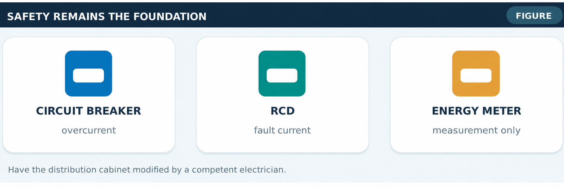
Have changes to the fixed installation performed, or at least checked, by a competent electrician under applicable standards and regulations. Turning off the main switch does not automatically de-energise every part of the cabinet.
After the work
Check covers, the protection used, operation of final circuits and RCDs, voltage references and whether the measurement device starts reliably.
Document it
Make a final-circuit list and record the precise channel, phase, device and firmware version.
Caution: This is a design and integration guide, not step-by-step instructions for working on live wiring.
16. What should you measure first?
A useful measurement system begins with a good question, not by filling every spare DIN-rail slot.
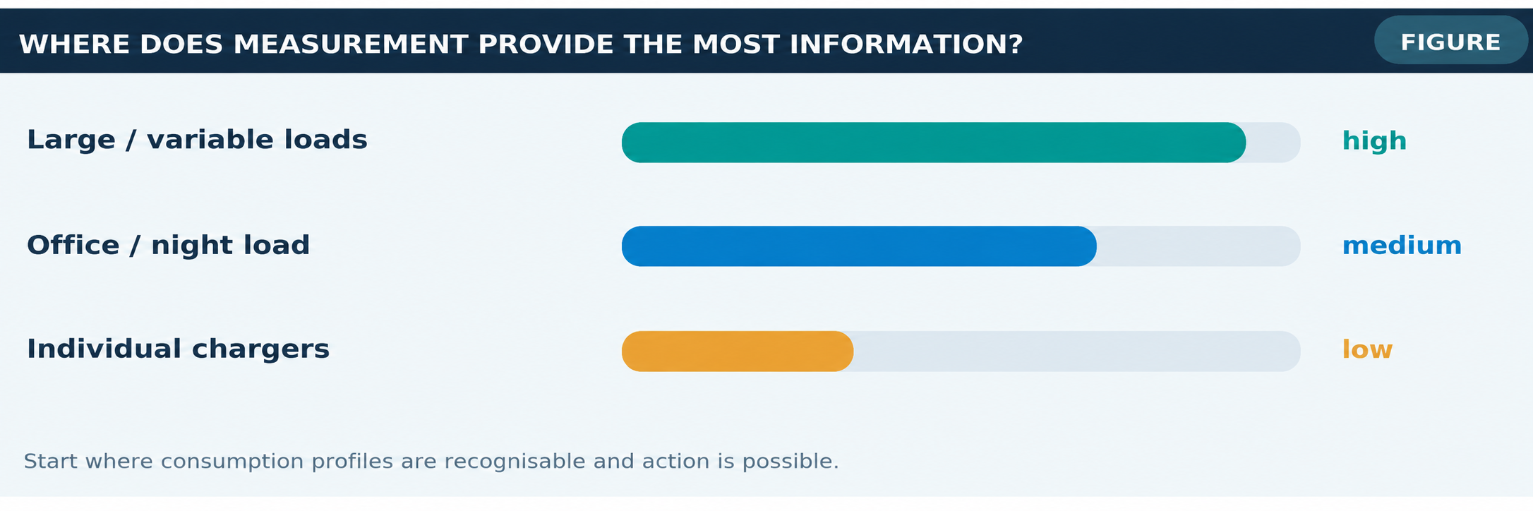
Priority A: circuits with substantial variation
Living room, office and kitchen sockets usually produce recognisable peaks. You quickly see whether a PC, kitchen appliance or multimedia system increases the baseline load.
Priority B: separate major consumers
A heat pump, electric boiler, EV charger or electric forced-air heating on its own circuit can be very worthwhile to measure. A dedicated measurement point is logical if the equipment has no reliable built-in meter.
Priority C: small continuous consumers
Routers, NAS devices, switches, standby electronics and adapters add up, but each is small. Their total consumption matters more than a momentary snapshot. Some CT solutions fall short here because of a no-load threshold.
Example inventory
- Circuit 4: living room, TV, audio and decorative lighting.
- Circuit 7: office, PC and network equipment.
- Circuit 9: bedrooms, chargers and lighting.
- Circuit 12: separate heat pump or ventilation system, if it really has its own electrical circuit.
Start small
Select one variable circuit, one with a continuous baseline and possibly one separate major consumer. Then compare at least a week’s historical data.
Caution: For very small standby loads, a temporary reading from a good smart plug may be cheaper and more accurate as a reference.
17. Validating measurement reliability
Before building dashboards, check that every sensor really represents the intended circuit.
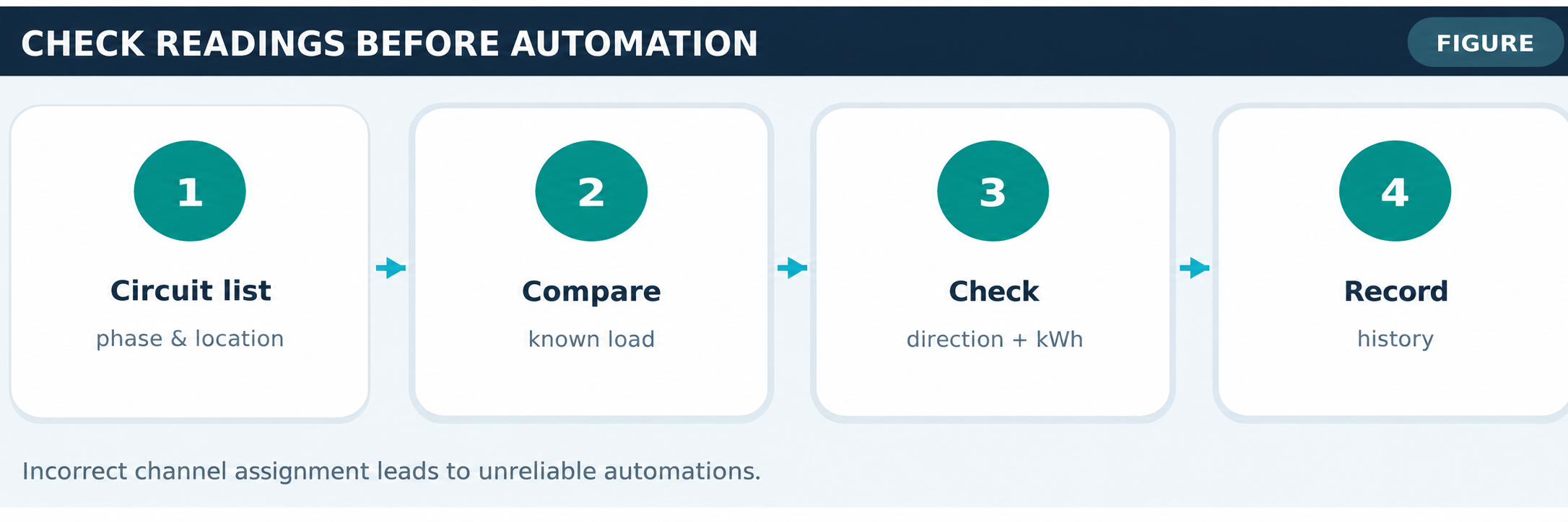
A usable validation protocol
- Record the final circuit, phase, CT model, firmware and sensor names for each channel.
- Check the zero-load reading. A genuinely empty circuit should show little or no power.
- Switch on one recognisable load on a selected circuit and check that only the correct channel rises.
- Where possible, compare temporarily with a second trustworthy meter.
- Check power direction during consumption and, if relevant, generation.
- Verify that the cumulative kWh counter increases at loads above the measurement threshold.
What differences are realistic?
Two meters need not match exactly. Measurement window, rounding, update frequency and measurement uncertainty can explain differences. Large systematic differences are more likely to point to wrong channel assignment, phase errors or unsuitable CTs.
Examine standby separately
Leave a circuit carrying only a few power supplies active for an extended period. If the W sensor reports a value while the kWh counter remains still, the system is unsuitable as an accurate cumulative energy meter in that range.
Only then automate
Use measurements for notifications or analysis only after establishing a stable baseline.
Caution: Use a known, safely applicable load for every test; do not make improvised electrical connections just to test a meter.
18. Connecting to Home Assistant
A meter’s value lies not just in the hardware, but especially in consistent entities and good history.
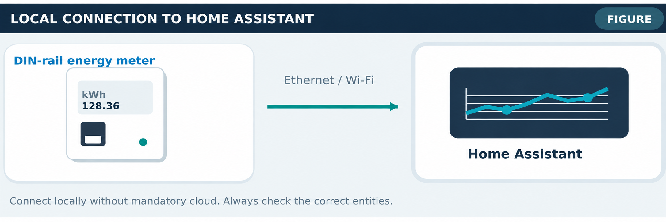
Add Shelly
Install the device and connect it to the local network. In Home Assistant, go to Settings > Devices & services > Add integration > Shelly. The official integration communicates locally with Gen2+ devices and does not require Shelly Cloud [7].
Add HomeWizard
Enable the local API in HomeWizard configuration if your device requires that. Then add the official HomeWizard integration in Home Assistant. Use the correct W and kWh sensors [10].
Modbus route
Use a supported meter and verify register addresses, data formats and polling. Home Assistant provides an official Modbus integration. A custom integration package can be convenient but brings extra maintenance [8].
Entity names
Name channels logically, for example sensor.groep_woonkamer_power and sensor.groep_woonkamer_energy. Your system determines the actual entity IDs; names in this guide are placeholders.
Device class and statistics
W sensors normally use device_class: power with state_class: measurement. Cumulative kWh sensors use device_class: energy with a suitable total or total_increasing class [11].
Network design
Reserve IP addresses through DHCP, keep meters reachable on the local network and test what happens when the internet connection fails.
Caution: Do not use two independent integration paths for the same physical measurement point if they create duplicate entities.
19. Energy dashboard and hierarchy
Choose consistently which sensor is the main meter and which sensors describe downstream consumers.
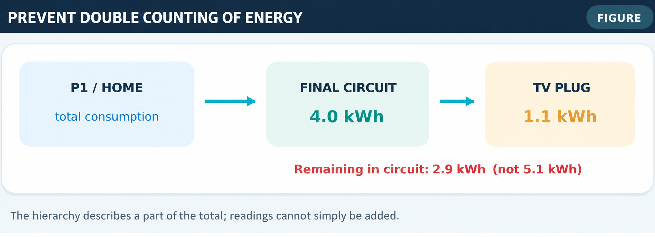
Set it up
Open Settings > Dashboards > Energy. Keep the P1/grid meter under Electricity grid and add final circuits under individual devices. If both kWh and W are available, you can also use the relevant instantaneous power data [9].
Upstream-device relationships
For example, the living-room circuit reports 4.0 kWh per day and a separately measured TV reports 1.1 kWh. The circuit is still 4.0 kWh. A sound hierarchy shows the TV as part of the circuit and the remaining 2.9 kWh as other usage, instead of presenting 5.1 kWh together.
Historical and current views
- Energy (kWh): day, week, month and year.
- Power (W): live load, peaks and night profile.
- Availability: latest received update and network status.
- Tariff analysis: estimated costs, if the time-dependent tariff is reliable.
Recording and retention
Check that Recorder stores the right entities. Also inspect statistics if a sensor is absent from the energy selector. The Energy dashboard uses long-term statistics [11].
Design tip
Give each dashboard circuit the same name as on the physical circuit list.
Caution: A circuit meter belongs below the house meter; a smart plug on that circuit belongs below the circuit meter.
20. YAML: adding circuit power readings
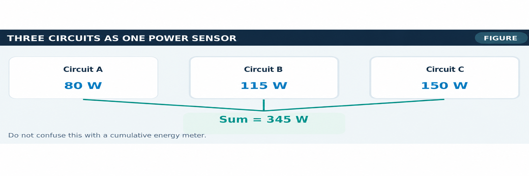
A template sensor is useful if you want to see the total instantaneous power of the circuits you measure.
template:
  - sensor:
      - name: "Measured circuits total power"
        unique_id: gemeten_groepen_totaal_vermogen
        device_class: power
        state_class: measurement
        unit_of_measurement: W
        availability: >
          {{ is_number(states('sensor.groep_woonkamer_power'))
             and is_number(states('sensor.groep_kantoor_power'))
             and is_number(states('sensor.groep_slaapkamers_power')) }}
        state: >
          {{ (states('sensor.groep_woonkamer_power') | float(0)
              + states('sensor.groep_kantoor_power') | float(0)
              + states('sensor.groep_slaapkamers_power') | float(0))
             | round(1) }}
What is this for?
This example adds three actual W sensors. It does not replace the P1 meter and shows only the sum of the selected circuits. Place it under template: in configuration.yaml or in a correctly included package.
Example
Replace the entity IDs with those in your installation. The availability check prevents a missing sensor from silently being counted as zero.
What not to do
Do not use this W sum directly as a kWh energy counter. For cumulative energy, use your meters’ own kWh sensors or an Integration helper if only a W sensor is available. Also avoid combining asynchronously resetting daily counters into one fictitious cumulative source [11].
Caution: This sensor shows only combined instantaneous power. Configure any circuit/appliance hierarchy separately.
21. YAML: unexpected baseline consumption
Circuit monitoring becomes truly useful when software recognises deviations without immediately switching equipment off.
alias: Office - high power while away
triggers:
  - trigger: numeric_state
    entity_id: sensor.groep_kantoor_power
    above: 80
    for: "00:30:00"
conditions:
  - condition: state
    entity_id: input_boolean.thuis_aanwezig
    state: "off"
actions:
  - action: persistent_notification.create
    data:
      title: "Unexpected office consumption"
      message: "Office uses >80 W while nobody is home."
mode: single
Scenario
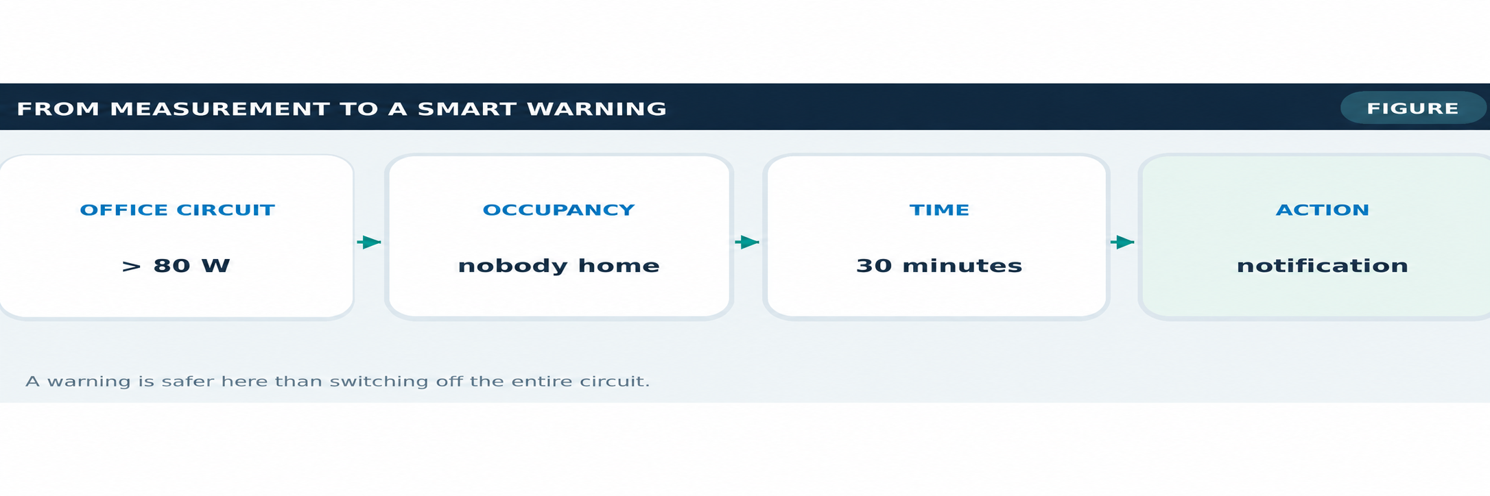
The office final circuit normally uses less than 30 W when nobody is home. A high load lasting half an hour may indicate a PC, monitor or power supply left on.
How does the automation work?
It responds only if power remains above the set threshold for half an hour while the occupancy helper is off. Its action creates a notification in Home Assistant.
Why not switch it off automatically?
An office circuit may also supply a NAS, router, phone system or other critical equipment. Measuring and alerting is safer first logic than blind switching.
Calibration
Measure normal night-time and away consumption first. Set the threshold above ordinary peaks. Use the for parameter to filter short fluctuations. Adapt the entities and helper yourself.
Further possibilities
Dynamic tariffs, historical medians and Solcast forecasts can support more complex advice, but that added intelligence does not change the underlying measurement quality.
Caution: Assess the normal consumption profile before defining thresholds.
22. Smart analysis: what can you recognise?
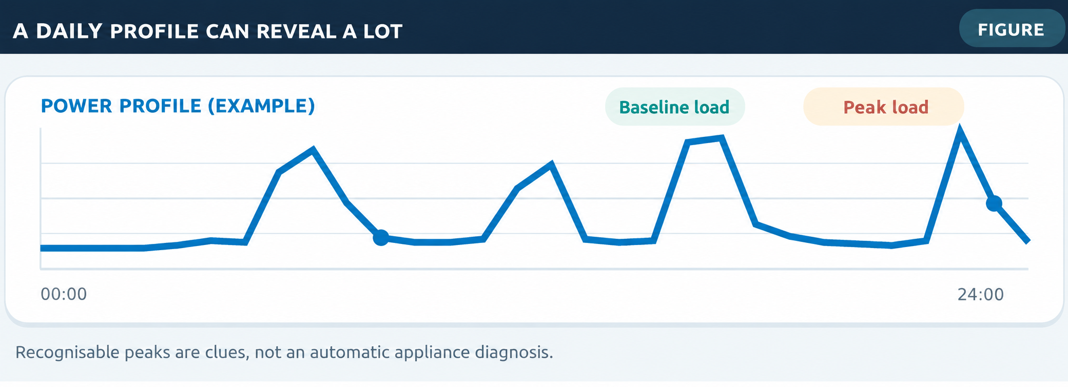
A circuit often has a recognisable daily rhythm even if you do not measure every plug separately.
Baseline load
A steady 35–60 W load throughout the night points to continuous consumers. You can test a hypothesis by deliberately switching off components over several days, without disrupting essential network or security functions.
Cyclic patterns
A refrigerator or freezer produces repeated compressor starts. Electric heating usually shows larger blocks. Some printers, PCs and media systems show characteristic start-up peaks.
Fault detection
Not every peak means a fault. More interesting is a sustained change in the pattern: a pump runs longer than normal, the ventilation baseline rises, or a standby circuit remains loaded after a firmware update.
Python can help
You can use AppDaemon, pandas and historical Home Assistant data to calculate each circuit’s daily median, night baseline, peak duration and change from the previous week. Keep the analysis advisory: a suspicion is not appliance identification.
Example signals
- Night baseline 40 W above the preceding two weeks.
- Office load remains above 150 W for 60 minutes while nobody is home.
- A regular pump cycle takes twice as long as usual.
Important limitation
CT data for an entire circuit reveal patterns, not a conclusive diagnosis of one connected appliance.
Caution: Use anomaly detection as an indication and verify the cause before acting.
23. What is the financial benefit?
More insight is valuable, but measurement equipment should not cost more than you can realistically save.
Example A: standby consumption
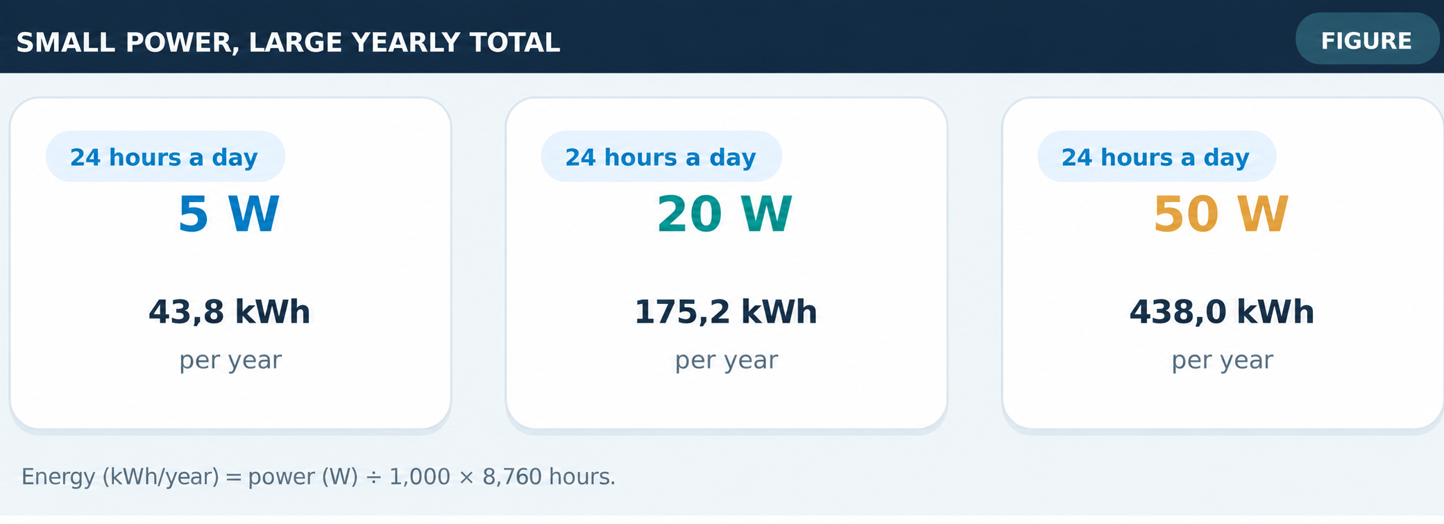
A continuous 20 W baseline is 0.020 kW × 24 × 365 = 175.2 kWh per year. At an assumed all-in electricity price of €0.30/kWh, that is about €52.56 per year. Eliminating an unnecessary half saves about €26.28.
Example B: only 5 W
Five watts continuously is 43.8 kWh per year, or €13.14 at €0.30/kWh. A complex measurement system for that load alone is unlikely to pay for itself quickly.
Cost items
The true investment includes the meter, CTs, installation material, DIN-rail space, a possible network cable and an electrician’s labour. Include the meter’s own electricity use too.
Where the main value lies
- Revealing unnecessary permanent load.
- Spotting an unexplained power peak or equipment fault earlier.
- Identifying an energy-intensive circuit during peak hours.
- Checking whether a targeted saving measure actually works.
Realistic payback
A measurement point is financially worthwhile chiefly if it leads to a behavioural change or exposes a technical problem. Measurement by itself saves no watt-hours.
Caution: €0.30/kWh is merely an illustrative assumption; dynamic prices and taxes make real savings variable.
24. Selection guide, checklist and sources
The best solution is the one that answers your question—even for small loads—without making the electrical system more vulnerable.
Final advice
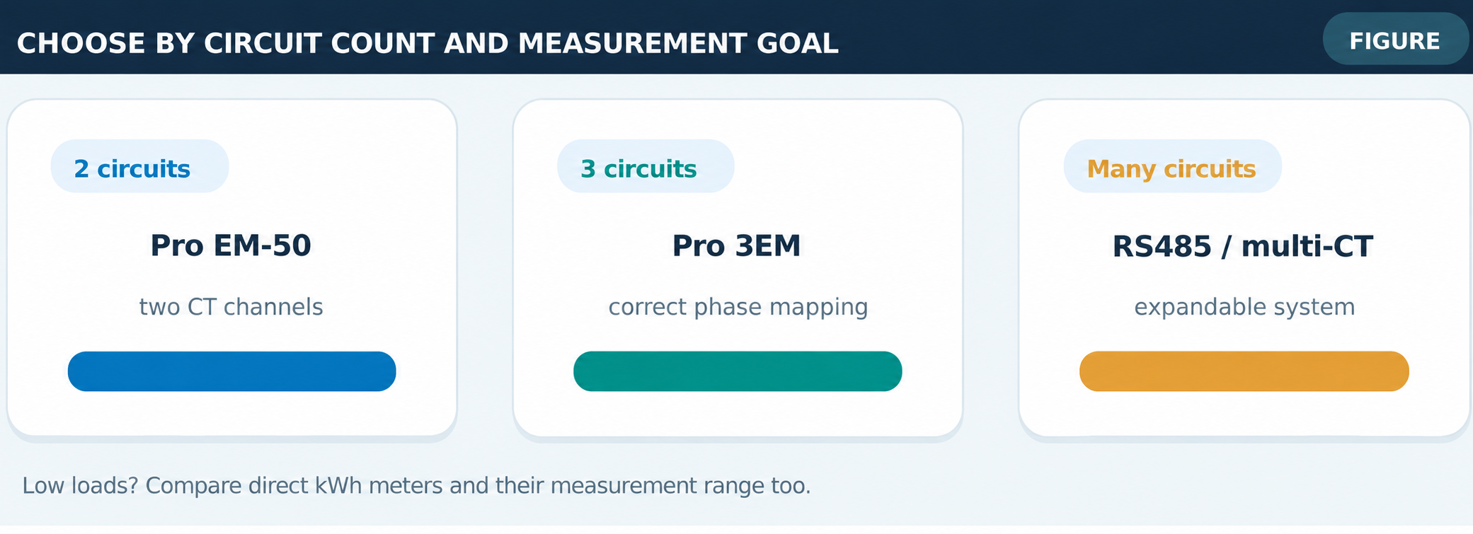
Two final circuits: start with a Shelly Pro EM-50 or, if accurate low-load kWh comes first, two suitable direct DIN-rail meters. Three higher-load circuits: a Pro 3EM may fit if its voltage references and configuration are correct. Many circuits: examine OpenEnergyMonitor or a network of individual Modbus meters. Use P1 for the whole-home total and smart plugs only where appliance-level detail genuinely adds value.
Pre-purchase checklist
- Know the exact number of final circuits and their phase assignment.
- Choose a measurement method suited to the expected minimum load.
- Confirm sufficient cabinet and installation space, certified power and enclosure.
- Check local Home Assistant integration and history.
- Avoid switching dependencies without a separate safety analysis.
- Have an installer and product-specific documentation available.
Selected primary sources
- [1] Shelly Pro 3EM: https://kb.shelly.cloud/knowledge-base/shelly-pro-3em
- [2] Shelly Pro EM-50: https://kb.shelly.cloud/knowledge-base/shelly-pro-em-50
- [3] Shelly EM Gen3: https://kb.shelly.cloud/knowledge-base/shelly-em-gen3
- [4] HomeWizard: https://www.homewizard.com/nl/kwh-meter/
- [5] Home Assistant Modbus: https://www.home-assistant.io/integrations/modbus/
- [6] OpenEnergyMonitor: https://openenergymonitor.org/docs/integrations/home-assistant.html
- [7] Home Assistant Shelly: https://www.home-assistant.io/integrations/shelly/
- [8] Home Assistant Modbus: https://www.home-assistant.io/integrations/modbus/
- [9] Home Assistant device hierarchy: https://www.home-assistant.io/docs/energy/individual-devices/
- [10] Home Assistant HomeWizard: https://www.home-assistant.io/integrations/homewizard/
- [11] Home Assistant Energy FAQ: https://www.home-assistant.io/docs/energy/faq/
Source publication version: 15 October 2026. Technical specifications, firmware and prices can change. All figures are schematic, not wiring diagrams.
Caution: Have a competent electrician assess the electrical suitability and safety of the distribution cabinet before implementation.