

Bambu Studio has hundreds of parameters, but a setting only helps when you know which problem it solves. This reference uses Bambu Studio 2.8.x terminology. When the official releases page was checked on 1 November 2026, 2.8.2.61 was the most recently listed public stable release and 2.8.4 was a public beta. Menus and defaults may vary by release, printer, and profile. If you are new to the slicer, start with the step-by-step guide to a good print.
From printer and filament presets to quality, strength, speed and support.
Start at the correct preset level
The printer preset describes hardware, the filament preset material behaviour, the process preset toolpaths, and object/modifier settings local exceptions. Fix a problem as close to its cause as possible. A wrong global profile often makes later prints worse.
Where are these settings? In Prepare, select the matching printer/nozzle, filament, and process profile. The printer preset describes the physical hardware. Temperature, Flow Ratio, and Maximum Volumetric Speed (MVS) primarily belong to the filament profile. Quality, Strength, Speed, and Support belong to the process profile. Object settings and modifiers are for local exceptions. Exact controls may differ across Bambu Studio versions.
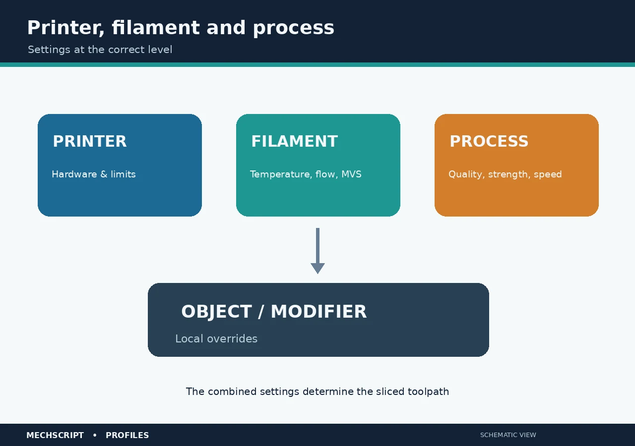
A printer preset contains nozzle diameter, build volume, machine limits and start/end G-code. Change these only when the hardware really differs and you understand the consequences. Never override bed or collision zones merely to slice an oversized model. Machine G-code is not an ordinary tuning knob: keep a clean original and test changes deliberately.
| Printer setting | Function | When to change it |
|---|---|---|
| Nozzle diameter | Determines available line widths, detail and flow capacity. | Only after a physical nozzle change. |
| Printable area/plate | Defines usable bed area and exclusion zones. | Do not enlarge it to force an oversized model through slicing. |
| Machine limits | Limits for speed, acceleration and firmware-dependent movement. | Only with a sound reason and machine knowledge. |
| Start/end G-code | Controls homing, heating, purge, fans and ending sequence. | Change narrowly, simulate and test. |
Incorrect machine G-code can cause unsafe movement, wrong temperatures or unwanted fan/AMS sequences. Always keep an untouched original of the official machine preset.
Filament: heat and flow
Nozzle and bed temperature affect bonding, detail, shrinkage and the first layer. Flow ratio corrects how much material is extruded; flow dynamics/pressure advance corrects pressure response during acceleration; max volumetric speed (MVS) limits the plastic volume per second. These are distinct. A high nominal travel speed does not help if the filament profile cannot supply the required mm³/s.
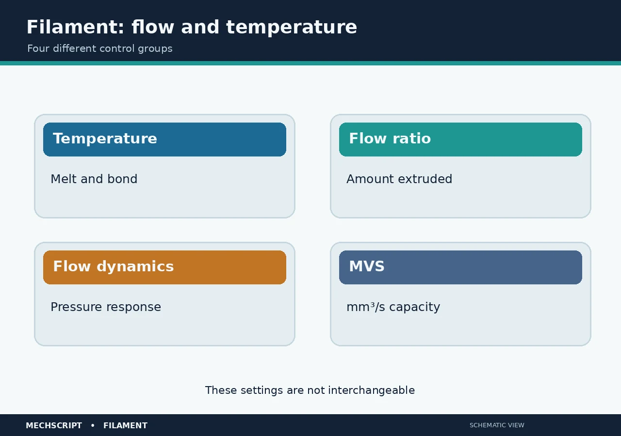
Cooling helps detail and overhangs, but too much can harm layer bonding. Minimum layer time slows tiny layers for cooling. Density and cost support estimates, not toolpath quality. Calibrate flow and MVS for the specific filament; do not blindly copy a profile to another blend.
| Filament setting | Function | Practical effect |
|---|---|---|
| Nozzle temperature | Melt temperature for normal layers. | Too low harms bonding and flow; too high may cause oozing and softened detail. |
| Initial layer temperature | Temperature of the first layer. | May improve adhesion but must suit the material. |
| Bed temperature | Temperature for the selected build plate. | Affects adhesion, shrinkage and elephant foot. |
| Flow Ratio | Corrects the total amount extruded. | Small differences can strongly affect surfaces. |
| Maximum Volumetric Speed | Caps requested mm³/s. | Too high causes under-extrusion in fast sections. |
| Cooling/part fan | Cools newly deposited plastic. | More may help detail; less can improve layer bonding. |
| Minimum layer time/slowdown | Lets small layers cool sufficiently. | Important for towers and fine features. |
| Density/cost | Estimates weight and expense. | Does not change toolpath quality. |
Flow Ratio, pressure advance/Flow Dynamics and MVS answer three separate questions: how much plastic, how pressure responds to acceleration, and how much volume per second can be delivered. A fault at one level is not safely corrected by an arbitrary setting at another.
Quality: resolution and surface
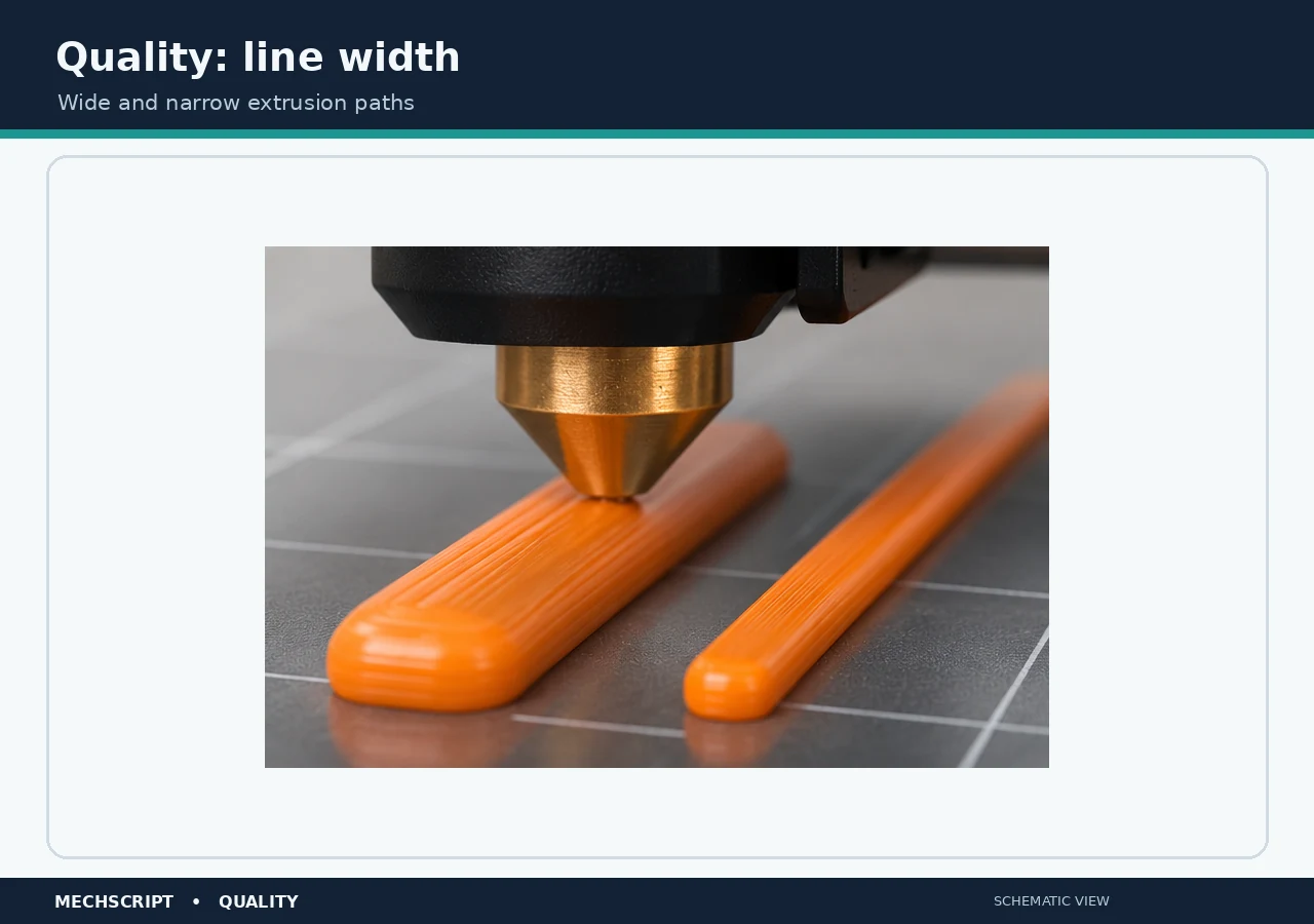
Layer height primarily changes Z resolution and print time, not XY detail directly. With a 0.4 mm nozzle, 0.12-0.24 mm is a common working range; extremes require suitable profiles. Initial layer height should favour reliable bed adhesion. Line width can differ for outer wall, inner wall, infill, top surface and first layer; change it deliberately and inspect Preview.
Example: comparing layer heights. Slice the same model with the same 0.4 mm nozzle, first at 0.28 mm and then at 0.16 mm layer height, using otherwise matching profiles. Compare visible layer lines, inclined surfaces, and estimated print time in Preview. This is a comparison, not a recommendation that either height is always superior.
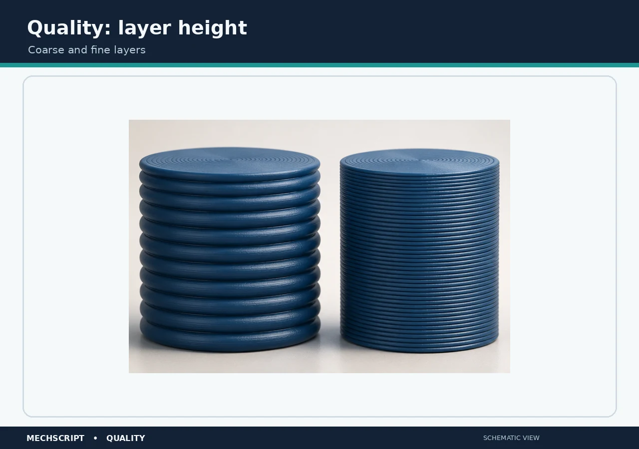
Lower layers follow slopes more closely and can improve overhangs, but quickly increase print time. XY detail is limited mainly by nozzle, line width and motion/toolpath behaviour. Do not make the first layer extremely thin for cosmetic reasons: its reliability matters more. Wide lines build walls faster with more plastic per line, while narrower lines offer more geometric flexibility. Leave preset widths alone unless solving a specific problem.
The Classic wall generator mainly uses fixed widths and gap fill; Arachne varies line width for thin geometry. Neither is universally better. Seam position controls the start/stop line: aligned, back and random distribute it differently. Scarf seam spreads the transition, but inspect thin or complex geometry.
Upstream configuration describes Arachne as a variable-width engine, while some official profiles still use Classic. Inspect what your functional geometry actually becomes in Preview. An aligned seam creates one predictable vertical line; back moves it to a rear side and random spreads small imperfections. Scarf seam may improve round display faces, but is not universal for every thin wall.
XY hole and contour compensation correct holes and outer dimensions. Use them only after flow and mechanical dimensions are stable. Elephant foot compensation corrects widened first layers; too much narrows the foot. Detect thin wall/precision features can save narrow shapes but overlaps partly with Arachne. Ironing smooths a top surface with low flow and costs time; fuzzy skin adds texture but changes dimensions. Use a modifier to protect mating faces.
Hole and contour compensation are distinct XY corrections: one for openings, one for outer size. Measure which error exists before using them, otherwise you may hide an extrusion or mechanical issue. Thin-wall detection depends on the wall generator because Arachne already uses variable line width. Ironing depends on flow, spacing, speed and selected top surfaces; excess flow can leave ridges or discolouration. Fuzzy skin can visually mask layer lines and improve grip, but should stay off dimensionally critical mating surfaces.
Strength: shell and core
Wall loops sets the perimeter count; for bending and joints, a thicker shell often helps more than extra infill. Top and bottom shell layers/thickness make solid skins and can strengthen thin panels. Sparse infill density of 15-25% is a useful starting range for many ordinary parts, not a fixed strength guarantee. Choose pattern by purpose: gyroid or cubic for multidirectional loads, grid with attention to crossing lines, lightning mainly for lightweight top-surface support.
Example: a functional bracket. Slice the same mounting bracket with two wall loops and then with five. In Preview, inspect whether the additional walls actually fit, how much more material is used, and how print time changes. Do not infer a guaranteed tensile strength: print orientation, material, layer bonding, and loading direction matter at least as much.
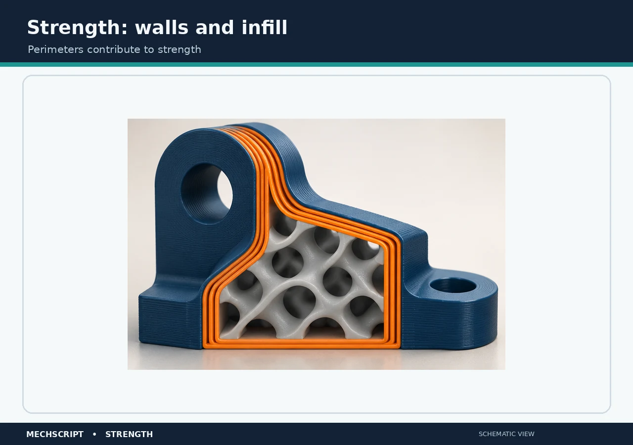
Check in Preview how many wall lines really fit: geometry and Classic/Arachne influence the result. Too few top shells can cause pillowing or visible infill; a substantial top or bottom skin can also stiffen a thin panel. Grid crosses lines within one layer, potentially causing build-up or nozzle contact on some machines. Gyroid follows smooth paths, while cubic offers a three-dimensional structure. Lightning saves plastic but mainly supports top surfaces rather than serving as general mechanical infill.
Infill/wall overlap controls how core and shell bond; too little bonds poorly, too much may show bumps. Wall/infill order affects dimensions, overhang support and outer finish. Only one wall on top surfaces can look cleaner but change thin functional areas. Inspect how many actual lines fit the geometry. See also why a 3D print is strong or weak.
Change overlap only after establishing a real core-to-wall bonding problem. Inner/outer/infill is a safe starting order. Outer-first can hold the outer dimension more accurately, but leaves that outer wall with less support on overhangs. Some presets restrict the wall count on top surfaces for a neater pattern; this can change the local structure of thin functional skins.
Speed: more than one mm/s number
Initial layer speed favours reliability; outer wall speed affects finish and dimensions; inner walls and sparse infill can often run faster. Excessive internal solid infill flow may undermine the top surface. Top surface speed influences smoothness. Bridges and overhangs need their own speed and cooling because they have little support. Fast travel can limit stringing but may increase vibration or nozzle contact. Acceleration determines whether a short move ever reaches its nominal speed; lower outer-wall acceleration can reduce ringing. MVS in the filament profile still caps requested volumetric flow.
| Speed field | Why assess it separately? |
|---|---|
| Initial layer | Slower printing gives plastic time to bond to the bed; this is rarely the right place to save seconds. |
| Outer wall | Affects visible finish and dimensions; slower movement may limit ringing and flow demand. |
| Inner wall | Can be faster than outer walls, but MVS still limits it. |
| Sparse infill | May run fast, though extreme acceleration, nozzle contact and flow shortfall remain possible. |
| Internal solid infill | High volumetric demand can cause under-extrusion directly below the top surface. |
| Top surface | Lower speed often improves smoothness and consistent line spacing. |
| Bridge | Too slow can sag; too fast can break the line or reduce bonding. |
| Overhang | Targeted slowing is often better than slowing the entire print. |
| Travel | Less travel time can reduce stringing, but increases dynamic loading. |
| Acceleration | Determines whether a short section reaches nominal speed at all. |
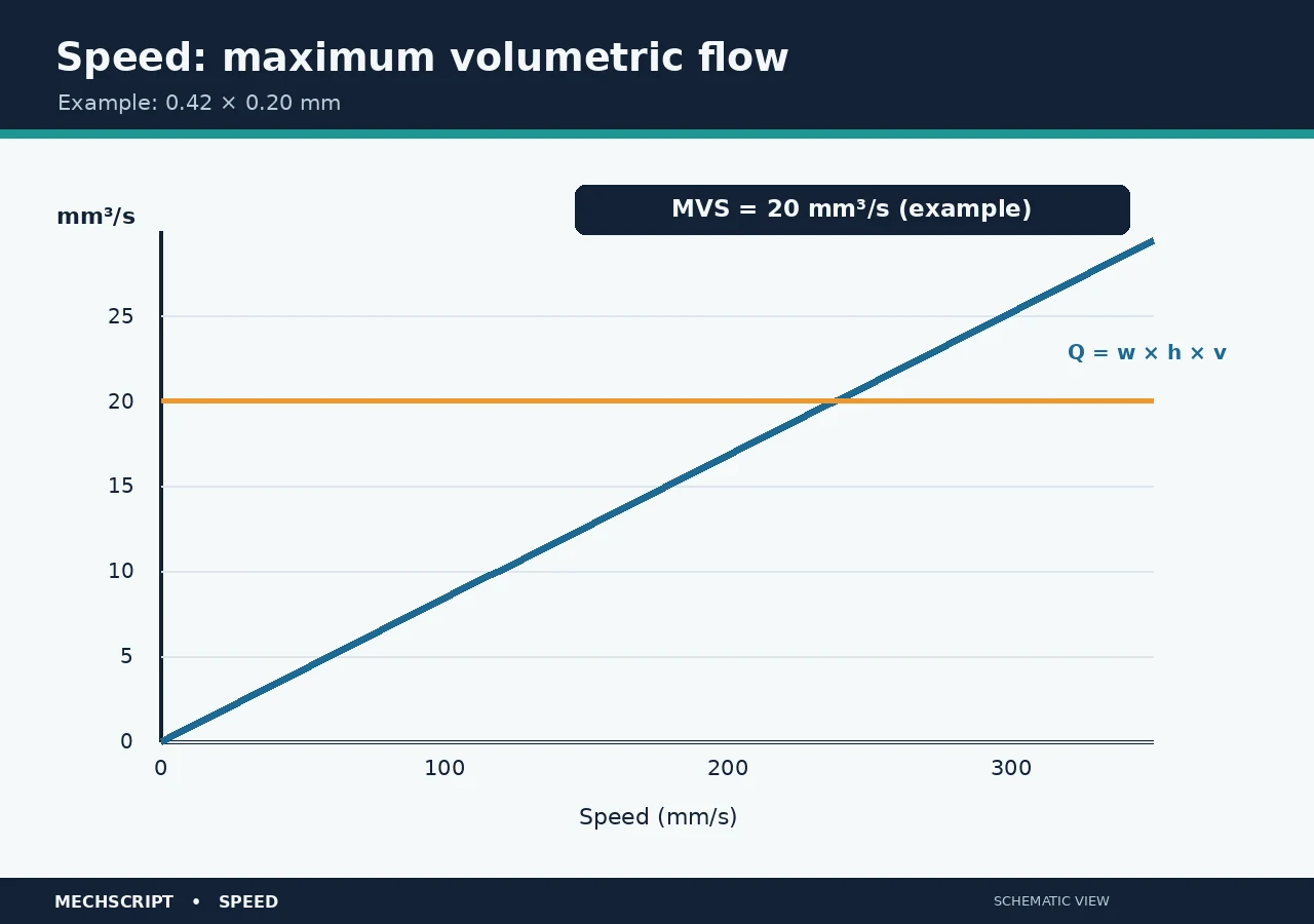
Volumetric demand is approximately line width × layer height × mm/s. A '500 mm/s printer' with a thick 0.28 mm layer and wide lines may therefore run much slower because of MVS. That is a material-and-hotend limit, not a defect in the speed preset.
MVS example: with a 0.42 mm line width, 0.20 mm layer height, and 200 mm/s speed, the requested flow is about 16.8 mm³/s (0.42 × 0.20 × 200). If the filament profile has an MVS of 20 mm³/s, the theoretical flow-limited speed for this combination is about 238 mm/s. Actual speed also depends on acceleration, geometry, and other limits. The 20 mm³/s limit is an example, not a general MVS recommendation.
Supports and other options
Support balances geometry, underside finish, time and removal. Normal support is predictable for flat areas; tree often works efficiently around organic shapes. Threshold angle, build plate only, interface layers and spacing control where and how support forms. Top Z distance and object XY distance control separation: smaller gaps can improve supported faces but make removal harder. A different AMS interface filament can help, at the cost of changes and waste. Check tree branch diameter and angle for stability.
| Support setting | Meaning and trade-off |
|---|---|
| Enable support | Auto is a starting point; painting support gives targeted control. |
| Normal/tree | Normal is predictable for flat regions; tree is often efficient around organic forms. |
| Threshold angle | Decides when an overhang needs support; check how your UI defines its angle. |
| Build plate only | Prevents support starting on the model, but may leave regions unsupported. |
| Top Z distance | Smaller vertical gap often makes the underside neater but harder to separate. |
| Object XY distance | Smaller lateral gap improves support but can leave more scars. |
| Interface layers/spacing | A denser interface may improve the underside, at a cost in time and material. |
| Support/interface filament | A different AMS material may release more cleanly, with purge and time overhead. |
| Tree branch angle/diameter | Too thin may break; too thick takes time and is harder to remove. |
Preview check: slice an overhanging model once without support and again with the necessary support. Inspect whether supports reach the correct surface, grow from a stable base, and avoid important visible faces. Focus on Top Z distance, Object XY distance, and the interface. A smaller gap is not automatically better: supports can become harder to remove.
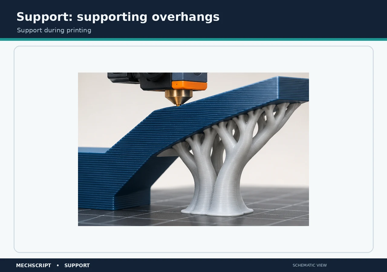
Do not begin with support density: vertical and lateral distances from the model often matter more to finish and removability.
A skirt primes and shows the first extrusion without touching the model. A brim increases bed contact; brim-object gap balances adhesion against removal. A raft is heavier and often harms underside finish and dimensions. Prime/wipe tower supports colour or material changes but uses material and bed space. With print sequence by object, the printer preset must confirm safe extruder clearance. Spiral vase makes one continuous thin wall and is usually unsuitable for functional multiwall parts.
Modern Bambu machines often have an extensive purge sequence already, but a skirt visibly confirms the first layer starts well. A brim is most useful for narrow feet, tall parts and shrink-prone materials. A raft uses several layers underneath and is justified only when plate cleaning, correct adhesion and a brim do not suffice for that geometry. Tower width, volume and position affect waste, reliability and available bed space; the 2.8.x line includes automatic placement improvements. By-object printing can save colour changes, but never override the collision zone to crowd the plate. Spiral vase fundamentally changes the structure: one continuous spiral wall instead of ordinary layers and seams.
Modifiers, calibration and diagnosis
Use object settings or modifier meshes for extra walls near a bolt hole, slower visible surfaces or support under one overhang instead of changing the whole profile. Calibrate in this order: clean plate/nozzle and dry filament; suitable temperature range; flow ratio; flow dynamics; MVS; only then walls, speed, support and detail. Automatic calibration varies by printer model.
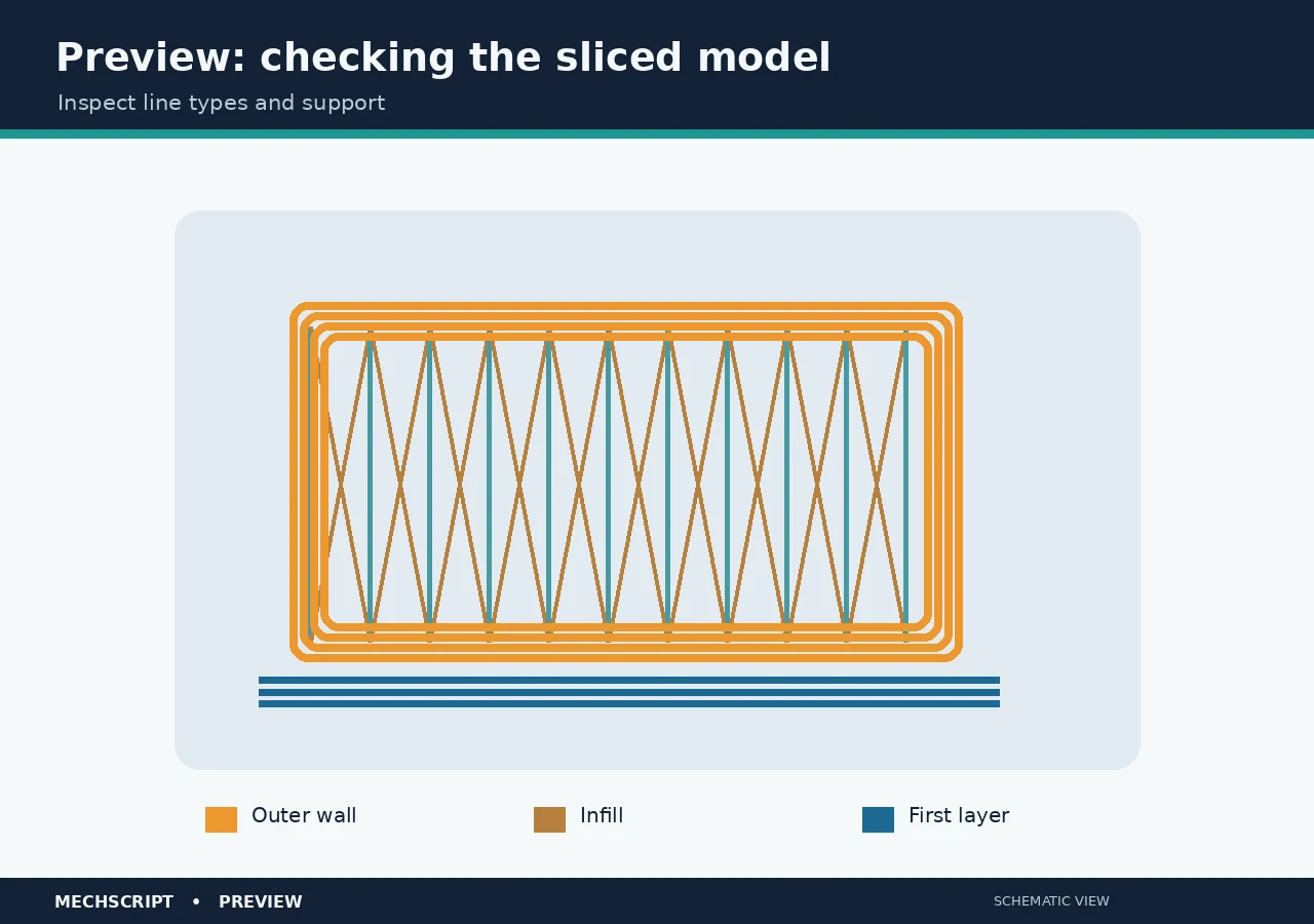
Check Preview: after slicing, switch between line type, speed, and volumetric flow. Look at where the slicer places outer walls, infill, supports, and material changes. A clean-looking model in Prepare does not guarantee a correct sliced toolpath.
| Problem | Check first | Only then adjust |
|---|---|---|
| Stringing | Dryness and temperature | Retraction, wipe, travel. |
| Visible seam | Seam placement and flow | Scarf seam, wipe and model orientation. |
| Small holes | Flow and consistent dimensions | XY hole compensation. |
| Poor supported overhang underside | Orientation and need for support | Overhang speed, cooling, support Z gap and interface. |
| Rough top | Flow, top shells and infill support | Top speed, ironing. |
| High-speed under-extrusion | Filament path, nozzle, temperature | MVS or suitable hotend capacity. |
| Ringing | Mechanics and resonance | Outer wall speed/acceleration. |
| Weak part | Orientation, material and layer bonding | Wall loops, shells and local infill. |
| Warping | Clean plate, temperature, drafts | Brim, enclosure, cooling. |
Beginners should leave machine G-code, arbitrary machine limits, several simultaneous compensations, extreme MVS, zero support gaps and default 100% infill alone. Change one parameter with a hypothesis, slice again and inspect Preview for line type, speed, volumetric flow, fan, layer time and tool changes. Then print a test. Preview shows what the printer will actually attempt.
Three practical profile mindsets
| Goal | Priorities | Typical targeted changes |
|---|---|---|
| Attractive display print | Outer surface, seam, top surface and detail. | Lower outer/top speed, deliberate seam placement, suitable layer height and possibly ironing. |
| Strong functional part | Orientation, material, layer bonding and walls. | More wall loops, appropriate temperature/cooling, local modifiers and moderate infill. |
| Fast prototype | Reliability, coarser resolution and less plastic. | Larger layer height, normal walls, low/moderate infill and fewer supports through orientation. |
These are priorities, not ready-made numerical profiles. Good profiles remain as general as possible, with exceptions localised to an object or modifier.
Quick reference and sources
| You want | Check first |
|---|---|
| More Z detail | Layer height. |
| More XY detail | Nozzle diameter, line width, Arachne/Classic and model resolution. |
| Stronger bracket | Orientation, wall loops, material and temperature/cooling. |
| Faster printing | Layer height, line width/nozzle, MVS, infill, speed and acceleration. |
| Better top surface | Top layers/thickness, top speed, flow and perhaps ironing. |
| Better supported underside | Support interface, top Z distance and possibly interface filament. |
| Less warping | Material profile, bed temperature, enclosure, brim and cooling. |
| Better dimensions | Flow Ratio, wall order, XY compensation and elephant foot. |
| Less visible seam | Seam placement, scarf seam, flow and wipe. |
| Less multicolour waste | Purge/flush, object strategy, colour order, tower and flush-into-object where suitable. |
For current versions and changelogs, consult the official Bambu Studio GitHub Releases. The official source code (src/libslic3r/PrintConfig.cpp) and preset files (resources/profiles/BBL/process/fdm_process_common.json) provide further detail on parameter definitions and shared process settings. For materials, consult the Bambu Lab Filament Guide and, most importantly, the TDS for the exact filament brand and variant. This guide supports technical decisions; it is not certification for safety-critical uses.