
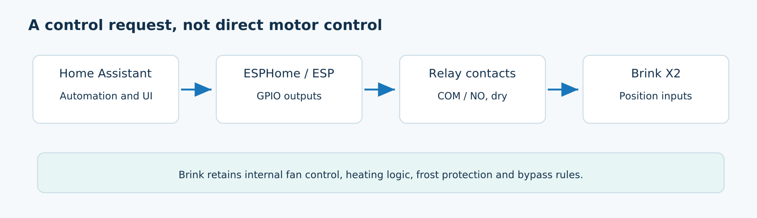
A practical guide to the D1 mini, ESP32, relays and Home Assistant.
A heat recovery ventilation (HRV) system can work for years with a simple speed selector. But that switch does not know when someone has just taken a shower, CO₂ is rising or everybody has left the house. A small ESP controller, a relay module and ESPHome let you bring control of a Brink Renovent Excellent 300/400 into Home Assistant. The Brink still controls its own fans, frost protection and bypass: in principle, this project automates only the selection of a ventilation setting.
Scope. This article concerns the Brink Renovent Excellent 300/400 and corresponding Plus variants with an X2 speed-selector connection. The pin functions follow a practical description of the Excellent and Brink’s X2 wiring diagram. Verify the unit revision, physical pin numbering and cable before connecting anything. Do not assume that other Renovent ranges, including older HR Medium/Large models, work the same way.
1. Why automate an HRV system?
The aim is not to ventilate as little as possible. The aim is to provide enough ventilation at the right time. An HRV system replaces indoor air while reducing heat loss through the extracted air. Lower ventilation may save electricity and heat, but prolonged under-ventilation increases the risk of unhealthy air, moisture problems and mould.
Smart control is most useful when it responds to a real demand for ventilation: a humidity spike in the bathroom, CO₂ in an occupied bedroom, cooking or a home that remains empty for a long time. Home Assistant can give air quality priority, enforce minimum run times and prevent needless switching between speeds.
What does not change? A relay on the speed-selector interface does not add sensors or motor control to the Brink. It does not automatically provide actual airflow, fan power, real bypass position, filter pressure drop or fault diagnostics. Those measurements require separate instrumentation or another demonstrably supported interface.
2. How does the Renovent Excellent work?
The Renovent Excellent contains two fans, a heat exchanger, filters, temperature sensors and a bypass damper. The supply fan brings filtered outdoor air into living spaces; the extract fan removes humid or polluted air from rooms including the bathroom, kitchen and toilet. The heat exchanger transfers heat between the two air streams without directly mixing them. Under favourable conditions the bypass can largely bypass the heat exchanger; this is not active air conditioning.
The Brink electronics handle frost protection and internal fan control themselves. The external switch requests a setting. According to official installation instructions 612010-Z, the factory airflow values are:
| Brink operating choice | Renovent Excellent 300 | Renovent Excellent 400 |
|---|---|---|
| Absence / minimum setting | 50 m³/h | 50 m³/h |
| Setting 1 | 100 m³/h | 100 m³/h |
| Setting 2 | 150 m³/h | 200 m³/h |
| Setting 3 | 225 m³/h | 300 m³/h |
An installer can change airflow values in the unit menu. The 300/400 model designation describes the range’s capacity; it does not mean that every high setting delivers exactly 300 or 400 m³/h. Check the actual configuration before making Home Assistant settings appear to represent specific airflow values.
Setting names: an easy trap
The Brink has absence/0 and settings 1, 2 and 3. Setting 1 is the default when none of the three selector contacts is active. You therefore need only two relays to select 1, 2 and 3. Selecting 0 requires a third relay. Some DIY projects number their user choices 1 through 4; do not confuse those labels with the Brink’s actual settings 0/1/2/3. The custom ESP32 PCB project explicitly calls them ESPHome positions: names for contact combinations, not necessarily the Brink’s setting numbers.
| ESPHome position | Relay contacts | Renovent Excellent in this installation |
|---|---|---|
| Position 1 | All NO contacts open | Setting 1, normal resting setting |
| Position 2 | X2 pins 2–3 closed | Setting 0, absence/minimum |
| Position 3 | X2 pins 2–4 closed | Setting 2 |
| Position 4 | X2 pins 2–5 closed | Setting 3 |
This functional mapping follows the unit- and project-specific practical pinout used for the Renovent Excellent 300/400. An actual Elan zone follows its own controller program; do not infer a fixed Elan setting or airflow from this table. All relays off is not the lowest possible Brink setting. Whether setting 0 guarantees the required minimum ventilation in your installation needs separate verification.
3. The official connectors: X2 is not eBus
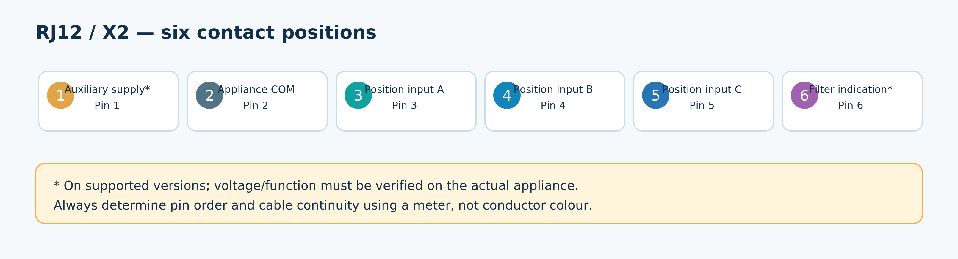
On the Excellent version discussed here, several connectors are located behind the display cover:
| Connector | Function | Used here? |
|---|---|---|
| X2 | Modular RJ12 connector for speed/setting control | Yes: relay contacts |
| X1 | Two-wire eBus, potentially OpenTherm depending on configuration | No: different interface |
| X15 (Plus) | Additional programmable contact and/or 0–10V functions | Comparison only |
| X14 (Plus) | Connection for pre-/post-heating | No; do not use |
Brink describes a six-core RJ12 cable for an optional four-position switch with filter indication. The manual mentions a four-core RJ11 for a simpler three-position switch without filter indication. It explicitly warns that X2 is intended only for low voltage. The X1 eBus connector is a different circuit; it must not be treated like a simple relay contact.
The functions of the six X2 contacts matter. RJ12 wire colours are not universal and reveal nothing about function until the cable has been tested. A 6P6C plug works only after verifying the cable connections and physical pin numbering.
Can the original selector remain connected?
Yes, in suitable configurations. The official Brink manual shows both a splitter with two controls and a combination of an RF receiver and an extra switch (§11.2.3 and §11.2.4). Use a splitter known to pass every required conductor through correctly 1:1, make sure the original RF module remains powered, and test what happens if two controls request different settings at the same time. A splitter is a passive parallel connection, not an intelligent priority controller.
4. The RJ12 plug explained: six contacts, six functions
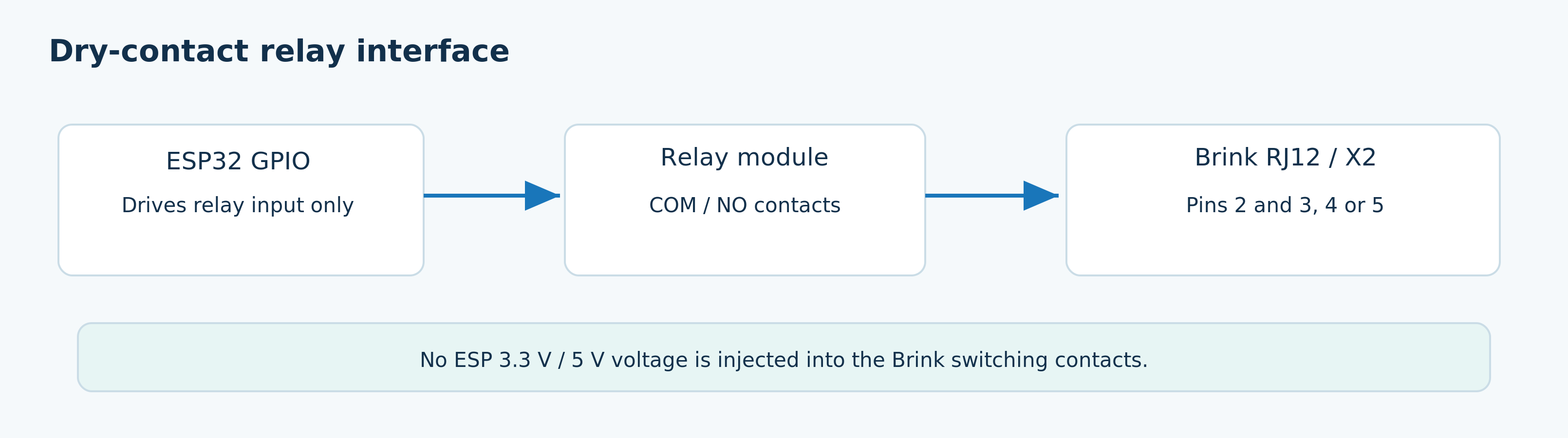
RJ12 is neither a communications protocol nor a sensor. It is the physical connector used by the Brink for a simple selector and, optionally, a filter light. The ESP does not replace RJ12; its relays provide the same electrical contact functions behind that connector.
RJ11, RJ12, 6P4C and 6P6C: what are you buying?
Online shops often use these names loosely. For modular plugs, 6P6C is more precise: six positions with six actual metal contacts. The common 6P4C has six positions but only four middle contacts. The plugs look similar and often fit mechanically in the same device socket.
| Name | Contacts | Example on this Brink |
|---|---|---|
| 6P6C, commonly RJ12 | All six positions present | Four-position selector with filter indication; complete breakout |
| 6P4C, often RJ11 | Four middle contacts, generally positions 2–5 | Three-position selector without filter indication |
| 8P8C, often RJ45 | Eight contacts; wider plug | Do not use for X2 |
A 6P6C connector has a plastic body, latch and six small plated contact surfaces. A suitable modular crimp tool presses those contacts through the insulation of the six wires. The plug does not determine their functions: the cable and the way it is crimped determine which wire reaches each contact.
How do you identify pin 1, and why do plugs appear mirrored?
Look at the loose plug from the side with the visible metal contacts, with the latch away from you/on the underside and the cable pointing towards you. In that defined view, the diagram counts from pin 1 on the left to pin 6 on the right. Turn the plug over, look into the device socket or reverse the front and back of an adapter, and the same row appears reversed. A 6 5 4 3 2 1 label on a schematic therefore need not contradict the numbers in a photograph of a loose plug. Stick to one defined viewpoint and verify actual pins with a cable tester or multimeter.
The six RJ12 pins on the Renovent Excellent 300/400
The following assignment was described by a Renovent Excellent 300/400 user on the MySensors forum and is consistent with the switching principle in Brink’s X2 drawing. It is a unit-specific practical pinout, not a standard for all Brink models. The technical revision clarifies that pin 1 is not connected on the custom PCB; that says nothing about the voltage which may be present at pin 1 on the Brink unit.
| Pin | Signal/function in this project | Meaning and safe connection |
|---|---|---|
| 1 | Possible internal +24V auxiliary supply on a supported unit | Not used on the custom PCB; do not connect to external 5 V or ESP power. Presence and current capacity are not universally proven. |
| 2 | Common/reference for this Brink channel | Only to COM of this channel’s voltage-free relay contacts. On the custom PCB: HRV GND1, upper Elan GND2, lower Elan GND3; not ESP-GND. |
| 3 | Selector contact A; setting 0 on this Renovent | Relay A’s NO contact closes only to pin 2. |
| 4 | Selector contact B; setting 2 on this Renovent | Relay B’s NO contact closes only to pin 2. |
| 5 | Selector contact C; setting 3 on this Renovent | Relay C’s NO contact closes only to pin 2. |
| 6 | Filter indication | Perhaps around 24 V on active indication; measure actual voltage and polarity on the Renovent/Elan first. Never connect directly to a GPIO. |
Where is setting 1? It needs no fourth wire. If the inputs for 0, 2 and 3 are all open, the Renovent described here normally chooses setting 1. No relay for setting 1 is needed.
The roughly 13 V on open setting-2 and setting-3 inputs reported in the forum is a user measurement, not a guaranteed or loadable supply voltage. The same applies to the roughly 24 V filter signal. Never connect 24 V or 13 V directly to an ESP8266 or ESP32 GPIO. The Brink’s GND is not protective earth and need not be connected to ESP-GND. Nor may the three Brink commons be tied together merely because their names look similar.
How the contacts connect to the relays
In the diagram each relay has its own NO (normally open) contact. All COM contacts connect only to pin 2 on the associated Brink side. The NO contact closes the requested setting input to pin 2. NC is not used in this design. Power for the relay coils or drivers remains electrically separate from the contacts.
| Selected Brink setting | Setting-0 relay | Setting-2 relay | Setting-3 relay | Closed contact pair |
|---|---|---|---|---|
| 0 — Absence | On | Off | Off | Pins 2–3 |
| 1 — Low/rest | Off | Off | Off | None |
| 2 — Medium | Off | On | Off | Pins 2–4 |
| 3 — High | Off | Off | On | Pins 2–5 |
Setting 0 does not guarantee a safe ventilation rate. According to Brink documentation, its behaviour depends on the configured minimum-flow parameter and may, under some settings, mean a stopped fan. Use setting 0 only when the ventilation the home actually needs remains assured.
What do the colours in an RJ12 cable mean?
There is no universal Brink colour code saying that red means 24 V, black means GND or yellow means high. Colours in flat telephone cable vary by manufacturer and batch. Brink explicitly notes that the core colours in its RJ12 example can differ; so does the forum example. For your own documentation, fill in a table for a cable with six visible colours. It is a measurement form, not a universal wiring diagram:
| RJ12 pin | Function in this Renovent setup | Colour in your cable — fill in yourself |
|---|---|---|
| 1 | Possible internal auxiliary supply | … |
| 2 | Common | … |
| 3 | Setting 0 | … |
| 4 | Setting 2 | … |
| 5 | Setting 3 | … |
| 6 | Filter indication | … |
For example, blue might be pin 2 in one cable but pin 5 in another. Both cables can be suitable if their actual connections are correct. An instruction such as “connect blue to COM” is unsafe without measurement.
Straight-through or mirrored? Check both ends
A cable may connect pin 1 to 1, 2 to 2, and so on, but another modular cable or adapter may reverse the order (1 to 6, 2 to 5, and so on). Two transparent plugs may look identical at first glance. Drawings with both latches held in a particular direction can also be optically confusing. Never trust a “telephone cable” solely because the plug shape fits. Check actual continuity with an RJ12 cable tester or a multimeter. If copying an original Brink cable, measure its connections rather than inferring the crimp order from wire colours.
Making an RJ12 cable: a practical sequence
- Choose six-core modular cable, matching 6P6C plugs and a crimp tool suitable for the solid or stranded conductor type and connector.
- Strip back only as much sheath as necessary. Keep the sheath beneath the strain relief and avoid nicking the wires.
- Arrange the six wires in the intended pin order and record the actual colour chosen for every pin.
- Push every wire fully to the front of the plug, check that every contact is filled, and then crimp it.
- Test each connection end to end. In addition to the six intended connections, check that neighbouring pins are not shorted.
- Test any splitter or RJ12 screw-terminal adapter too. Do not trust labels or terminal positions without verification.
- Only after the cable test passes, connect it to the powered-down Brink and first test the familiar original controller.
An RF receiver and ESP through a splitter
Brink’s §11.2 shows how an extra controller can be connected through a splitter. This can keep the original Brink RF remote while adding ESPHome. Use a splitter with verified conductor mapping; some modular telephone adapters have different or partial wiring. Test the RF module before and after connecting the ESP, and check each of the three active settings separately.
Concurrent RF and ESP requests have no guaranteed software priority: the signals are connected in parallel and the result depends on the Brink input logic. Arrange for the ESP contacts to fall open on failure and document whether manual operation is meant to take priority. A straightforward fallback procedure is useful: disconnect the ESP and reconnect the original control.
Filter indication: why treat pin 6 separately?
Pin 6 is not a fourth ventilation setting. It is feedback for the filter indicator on a compatible selector. It is an input for the ESP, whereas the setting contacts are made by relays. A suitable design reads this signal with a correctly dimensioned, preferably functionally galvanically isolated input such as an optocoupler. Such isolation is not automatically a certified safety barrier. Article 2 (RJ12/Elan) and article 3 (the custom PCB) cover that design in detail. A filter alarm does not continuously measure filter dirt and does not replace scheduled maintenance.
5. How a relay imitates the selector switch
An ESP GPIO supplies a 3.3 V digital signal. A GPIO is not a voltage-free contact. A relay has two separate sides: a coil or electronic control input driven by the ESP, and switch contacts (COM, NO and often NC) that can close an external circuit.
Use only the relay module’s dry COM/NO contacts on the Brink side; leave NC unused. Do not connect the 5V supply or ESP-GND to a Brink signal wire unless a specific validated design expressly requires it. An optocoupler or transistor is not automatically a substitute for a dry contact; those devices behave differently electrically.
Two relays are enough for Brink settings 1, 2 and 3. Selecting setting 0 requires a third. The illustrated X2 switching logic is that each requested selector contact closes only its own NO contact to pin 2; the other contacts stay open. The relay contacts are voltage-free. Software interlocking helps prevent more than one setting contact closing during normal operation, but it is not a hardware lock and proves neither safe boot behaviour nor protection against a welded contact.
D1 mini or ESP32?
A Wemos D1 mini (ESP8266) is inexpensive, compact and has enough GPIOs for one HRV unit. An ESP32 offers more connections and is attractive if you also want filter indication, extra relays or several devices. An ESP32 is not inherently better if you only need three selector contacts.
| Consideration | D1 mini (ESP8266) | ESP32 |
|---|---|---|
| Drive three relays | Possible | Possible |
| Spare GPIOs | Fewer | More |
| Extra signals | More limited | More flexible |
| Wi-Fi / ESPHome | Supported | Supported |
| Boot and strapping pins | Check carefully | Check carefully too |
| Logic voltage | 3.3 V | 3.3 V |
6. Parts and electrical preparation
For a first HRV setup, you need a D1 mini or ESP32, a suitable three-channel relay module or three separate relays, an isolated and suitable low-voltage supply, an RJ11/RJ12 breakout or correctly assembled plug, wiring, an enclosure, cable strain relief and preferably a multimeter. For a permanent installation, screw terminals, solid mounting and clear labels on every contact matter more than an attractive breadboard.
Check five things beforehand: (1) will the relay electronics respond to 3.3V GPIO logic, (2) does the module require 5 V or 3.3 V power, (3) is it active-high or active-low, (4) do the relays remain in the desired state on boot and loss of power, and (5) are the switch contacts electrically separate from the ESP control? Many 5V relay modules only partly implement optical isolation, or defeat it through a shared ground.
The custom HRV PCB in article 3 requires an external regulated 5V supply. Its design uses U5 (polyfuse), Q4 (AO3401) and U7 (AMS1117-3.3). Check the DC jack pins, MOSFET footprint and the correct 22µF output capacitor with a suitable type/ESR under load. The custom PCB also uses GPIO5 for buzzer driver Q3; this is an ESP32 strapping pin and needs a cold-boot test. GPIO18 is reserved for J8/future PWM; the header is not a ready-made fan driver. GPIO34 senses approximately half of VCC and needs ADC calibration. The UART service port uses 3.3V logic and cannot be attached to a 5V adapter without suitable conversion. These PCB details describe a design, not proof of a tested assembly.
230 V remains outside this build. Opening the unit, working on pre-/post-heaters or modifying mains connections is outside this guide. Power down the Brink according to the manufacturer’s procedure before changing connectors or working on the unit. Work only on the documented low-voltage interface.
7. Assembly and wiring: a workable approach
- Identify the exact unit: Excellent 300 or 400, standard or Plus, year and existing original controller.
- Record the existing wiring. Photograph the connector, cable and switch. First establish that the Brink works correctly with its original control.
- Test the disconnected switch with the power off. Determine which conductors the physical switch joins at each setting. Measurement on a connected or energised Brink requires a suitable procedure and expertise.
- Build the ESP and relays on the workbench. Test only the dry relay contacts with a multimeter. Observe the first seconds after power is applied too.
- Connect the confirmed contact pairs. Use only COM/NO and leave NC unused. Separately insulate unknown wires, including the filter indicator.
- Test one setting at a time. Begin with the resting state, then operate each relay separately and compare the Brink display with the requested setting.
- Test failure behaviour. Disable Wi-Fi, restart the ESP and briefly remove external power while the Brink is operating normally. Observe whether ventilation stays at an acceptable setting.
The power-loss state is a design requirement, not a detail. Three standard NO relays release when ESP power fails. The Brink then sees no closed selector contact and, in this connection model, returns to setting 1. You must assess whether that setting provides enough basic ventilation for your home. If not, use a differently designed resting contact, independent controller or monitored fallback. A software interlock and restore_mode: ALWAYS_OFF only become effective during firmware initialisation; before then the GPIOs are not yet under firmware control.
8. ESPHome example for a D1 mini
The following YAML demonstrates the logic for a D1 mini with three relays. GPIO5, GPIO4 and GPIO14 are example pins for the ESP8266. The code assumes an active-high relay module with dry NO contacts. For active-low hardware, adapt the output signal and, especially, test boot behaviour while disconnected from the Brink. The example uses setting 1 as its rest/start-up setting. If you never need setting 0, you can omit relais_stand0 and its selection, leaving two relays.
esphome:
  name: brink-wtw-relais
  friendly_name: Brink WTW relais
esp8266:
  board: d1_mini
logger:
api:
ota:
  - platform: esphome
wifi:
  ssid: !secret wifi_ssid
  password: !secret wifi_password
switch:
  - platform: gpio
    id: relais_stand0
    internal: true
    pin: GPIO5
    restore_mode: ALWAYS_OFF
    interlock: [relais_stand2, relais_stand3]
    interlock_wait_time: 200ms
  - platform: gpio
    id: relais_stand2
    internal: true
    pin: GPIO4
    restore_mode: ALWAYS_OFF
    interlock: [relais_stand0, relais_stand3]
    interlock_wait_time: 200ms
  - platform: gpio
    id: relais_stand3
    internal: true
    pin: GPIO14
    restore_mode: ALWAYS_OFF
    interlock: [relais_stand0, relais_stand2]
    interlock_wait_time: 200ms
select:
  - platform: template
    name: "Ventilatiestand"
    id: ventilatiestand
    optimistic: true
    initial_option: "1 - Laag"
    options:
      - "0 - Afwezig"
      - "1 - Laag"
      - "2 - Midden"
      - "3 - Hoog"
    set_action:
      - switch.turn_off: relais_stand0
      - switch.turn_off: relais_stand2
      - switch.turn_off: relais_stand3
      - delay: 250ms
      - if:
          condition:
            lambda: 'return x == "0 - Afwezig";'
          then:
            - switch.turn_on: relais_stand0
      - if:
          condition:
            lambda: 'return x == "2 - Midden";'
          then:
            - switch.turn_on: relais_stand2
      - if:
          condition:
            lambda: 'return x == "3 - Hoog";'
          then:
            - switch.turn_on: relais_stand3
The corresponding electrical contacts are: relais_stand0 closes pins 2–3, relais_stand2 closes pins 2–4 and relais_stand3 closes pins 2–5. All three remain open for setting 1. Prove the physical pin mapping of your actual cable before connecting it.
What does this configuration do?
restore_mode: ALWAYS_OFF sets an output off after start-up. During normal ESPHome operation, interlock prevents two of these relays from being commanded on at once. interlock_wait_time introduces a brief gap during a changeover. A select presents one clear choice in Home Assistant instead of three separate switches.
The optimistic: true setting means the displayed choice is the requested setting, not one confirmed by the Brink. There is no fan-setting feedback. This is also only a software measure: interlock cannot fix a physically welded relay or an unwanted boot pulse on a relay input.
Why not simply use GPIO0, GPIO2 or GPIO15?
On an ESP8266, strapping pins help determine the boot mode. A relay module can load one of those pins so that the ESP fails to start or operates a relay unexpectedly. ESP32 boards also have particular boot and input-only pins. Look up the manufacturer’s pinout for your board and test the complete supply/relay combination from a fully powered-down state.
9. ESP32 with several devices: the project configuration
The supplied ESPHome configuration uses an ESP32 to control three device groups. Its original YAML assigned HRV outputs 19, 27 and 26, lower Elan outputs 33, 25 and 14, and upper Elan outputs 32, 23 and 22. Each group contains three interlocked relays. The reviewed hardware/network mapping for the custom PCB makes the order by contact explicit:
| Unit and PCB connector | X2 pin 3 | X2 pin 4 | X2 pin 5 | X2 pin 2 / common |
|---|---|---|---|---|
| Renovent HRV / CN3 | GPIO26 | GPIO27 | GPIO19 | GND1 |
| Upper Elan / CN2 | GPIO32 | GPIO23 | GPIO22 | GND2 |
| Lower Elan / CN1 | GPIO33 | GPIO25 | GPIO14 | GND3 |
This is the project’s GPIO/net mapping, not a guarantee that a particular channel on an external relay module has been wired correctly. On the actual assembly, test J1/J2, the eight-channel module, the separate ninth relay and H1–H10. Keep the three Brink commons separate from ESP-GND and from each other; similar signal names do not make them electrically interchangeable.
The original YAML calls the state with all three relays off position1. That is the contact-free base position for the Renovent described here, but the three active HRV contacts correspond to Brink settings 0, 2 and 3. Labels WTW position 2/3/4 are therefore not necessarily Brink setting numbers. On each Elan zone, establish the meaning of a contact combination on the actual unit; do not assume a fixed Elan airflow.
The arrangement is understandable and a useful basis for a practical article. For a publicly reproducible design, one select with four choices per device, a tested start-up state, explicit priority logic and a clear description of the ninth relay would help: the provided PCB shows an eight-channel relay module plus one separately controlled relay.
GPIO assignments from this project are not a universal GPIO layout. The original YAML was made for a particular PCB and relay architecture. Software interlocking alone says nothing conclusive about physical contact protection. At cold boot, reset or supply sag, relays may behave differently from normal firmware operation; separately test active-high/active-low behaviour, simultaneous activation and welded contacts.
On the custom PCB, J7 selects the Elan filter line on pin 6 and J10 selects the corresponding common on pin 2. Both jumpers must choose the same zone: the reviewed design says 2–3 for upper or 1–2 for lower. Check the markings and physical orientation. Filter sensing uses 4.7 kΩ R1/R7, PC817 optocouplers, antiparallel 1N4148 diodes and BC858 PNP transistors; expected GPIO21/17 logic is 0/3.3 V, active HIGH on an alert. That is a design expectation, not proven for both Elan zones. Assuming +24.0 V and a 1.2 V LED forward drop, current through 4.7 kΩ is about 4.85 mA and resistor dissipation about 0.11 W. This calculation does not establish that pin 6 on every unit actually supplies +24 V; measure the voltage, polarity and behaviour first.
10. Connecting to Home Assistant
After flashing, the ESP normally appears under Settings → Devices & services → ESPHome. The Ventilatiestand select entity can appear on a dashboard as a dropdown or tiles. A useful interface may also show CO₂, relative humidity, Wi-Fi reception and the latest automatic command; CO₂ and humidity require separate sensors, not the relay controller.
Example: shower humidity boost
The Home Assistant automation below is a conceptual example. When an external bathroom sensor measures humidity above a configured threshold, the HRV switches to high. Entity names are examples. For production use, add detection of a relative humidity rise, a minimum run time and central priority logic. Otherwise humid outdoor weather or a competing automation may cause unnecessary switching.
alias: WTW - doucheboost (eenvoudig voorbeeld)
triggers:
  - trigger: numeric_state
    entity_id: sensor.badkamer_luchtvochtigheid
    above: 70
conditions: []
actions:
  - action: select.select_option
    target:
      entity_id: select.brink_wtw_relais_ventilatiestand
    data:
      option: "3 - Hoog"
mode: restart
This simple automation does not switch back automatically. That needs a separate, considered control rule. A fixed timer that switches back without checking CO₂ or humidity could end the boost too early.
Why priorities matter
Suppose a night programme sets the HRV to low at 23:00 while the bathroom is still humid. Without priorities, one automation overrides another. A more robust arrangement determines the highest current demand first: safety/minimum airflow, then CO₂/humidity, then presence, and only then comfort/energy saving. One central automation or script commands the select. Hysteresis and minimum run times reduce switching frequency.
11. Summer night ventilation and the Brink bypass
On a cool summer night, you might increase ventilation when outdoors is demonstrably cooler than indoors. That only helps if the air streams and bypass state are appropriate. A higher ventilation setting can move more outdoor air, but does not guarantee greater cooling. The built-in bypass has its own conditions and cannot be directly controlled by X2 relays.
A sensible night programme needs at least a representative indoor temperature, outdoor temperature, lower temperature limit and hysteresis. Better still is a decision rule that also considers the measured temperature change and the normal ventilation requirement. An X2 relay can affect airflow but cannot force the bypass into any chosen position.
12. Faults and safety: reason from failure modes
| Symptom | Typical cause | Check |
|---|---|---|
| Relay clicks on boot | Strapping pins or active-low input | Measure during a cold boot; change the pin/driver if necessary. |
| Relay does not energise | 3.3V signal unsuitable for a 5V module | Check datasheet, driver, supply and ground. |
| Two relays appear active | Wrong software, leakage current or defective module | Test contacts separately; inspect the hardware. |
| Brink responds differently than expected | Cable mapping or selector logic incorrect | Compare against the pin/switch matrix and original controller. |
| Wi-Fi is lost but the setting remains | ESPHome continues locally | Decide whether that is acceptable and provide a fallback. |
| Filter LED stays off | No filter-feedback circuit fitted | A separately validated input circuit is needed. |
| Home Assistant says “high” while the unit runs low | No actual unit feedback | Label the status as “requested”. |
A software interlock is not an electrical fail-safe. A physical failure, NC contact wired by mistake, unintended connection between selector circuits or lost supply calls for a responsible hardware design. The principle is that a single fault should not produce a dangerous state, and ventilation must not silently remain below the necessary minimum for a long time.
Electrical boundary. X2/RJ12 is only the intended low-voltage control interface. Do not inject external 5 V, 24 V or 230 V, or switch mains components through X2. The custom controller provides only voltage-free COM/NO contact closures. Keep Brink GND1/GND2/GND3 separate from ESP-GND; do not join them because of their names. Functional optocoupler isolation is not proven mains protective insulation.
Power down the units according to their manufacturer’s procedure before changing cables or connectors. Test the cable, relay contacts, power rails and start-up states while disconnected from the Brink. Do not rely on hearing a relay click: measure COM/NO with a multimeter. During use, check the actual airflow at the selected setting and avoid prolonged under-ventilation.
13. Test procedure before everyday use
Connect to the ESP first while leaving the Brink disconnected. With a multimeter, test each relay’s COM–NO and COM–NC in both rest and energised states. Check three cold starts, a software restart, loss of Wi-Fi, loss of Home Assistant and complete loss of ESP power. Observe the relay under power and the physical contact position without power. Include the active-low/high behaviour of the module actually used and the possibility of a welded contact.
Only then attach the proven contact arrangement to the powered-down Brink. Turn it on and check each setting on its own display; do not rely solely on fan noise. Also test reconnecting the original controller so that you can promptly return to existing operation if the project fails. The board has been reviewed as a schematic/PCB design. A fully populated assembly, long-term endurance, exact Elan filter signals, a safe boot state, EMC/CE and airflow commissioning have not been demonstrated.
14. What does it cost?
A D1 mini and small relay module are inexpensive components. A complete, safe installation also requires a power supply, connectors, insulation, an enclosure, mounting and a considered fallback. Budget the whole set of parts rather than just the ESP. Current retail prices vary considerably by supplier, relay module and enclosure, so this guide deliberately provides no unverified shop prices.
When does a custom PCB make sense? For one Renovent, a well-built ESP with relays is often enough. A designed PCB becomes more attractive when combining three units, filter indication, isolated inputs, a buzzer and future expansions. Article 3 covers that custom ESP32 PCB for a Brink HRV and Elan E.
Technical sources and provenance
- Practical X2 pinout: a MySensors forum contribution by ESPHA about a Renovent Excellent 300/400, describing six separate X2 pins, relays to pin 2 and an RJ12 splitter example. This is a user account, not a Brink factory guarantee for other models or revisions.
- Brink Climate Systems, Renovent Excellent 300/400 (Plus) installation instructions 612010-Z, particularly §3.1, §5.5 and §11.1–11.2. Factory values, connector designations and manufacturer warnings come from this document.
- Brink Elan E installation instructions Rev. C for the Elan references and the separate RJ12 guide.
- ESPHome: GPIO Switch, Template Select,
interlock,interlock_wait_timeandrestore_mode. The latter three describe software behaviour, not hardware guarantees. - Espressif’s ESP32 hardware design guidelines for strapping pins.
- Practical project source: supplied ESPHome configuration
esphome-web-d0df24.yamlwith an ESP32, nine relay functions and interlocks. The code in this article is a separate teaching example, not a literal copy of that configuration. - Original additional forum link: Let’s Control It forum, topic 5702. That site blocks automated access. The six-point account was independently found in the publicly accessible MySensors contribution and checked against the switching principle in Brink diagrams.
This article documents a private technical design for learning, understanding and individual assessment. It is not an official Brink instruction, a certificate or a declaration that a reproduced design is safe or suitable in every installation. Manufacturer instructions and applicable installation and product-safety requirements remain authoritative. Anyone building, modifying or connecting the circuit must choose suitable parts and power, assess risks and verify compatibility with the specific unit. Work on internal mains components is only for people with appropriate competence; this article does not authorise bypassing safety provisions. The author aims for accuracy but cannot guarantee an error-free schematic, safe application or uninterrupted availability. A disclaimer does not automatically exclude legal liability. Sale or distribution may trigger separate EU conformity, EMC, radio and product-safety requirements; this article is not legal conformity advice.
Related reading: Brink Renovent with ESPHome, Renovent and Elan E through RJ12 and the Brink-PCB controller. Project code and documentation.