
A functional FDM/FFF part does not become strong through one infill slider. Load, print orientation, geometry, walls, layer bonding and material together determine how it fails. A poorly oriented bracket with 100% infill can still split along its layer lines.
One hundred percent infill also adds weight, print time and internal stress. Think like a designer first: what force acts where, in what direction and how often? Choose material and slicer settings only after answering that. The order is load and geometry first, print-process optimisation second.
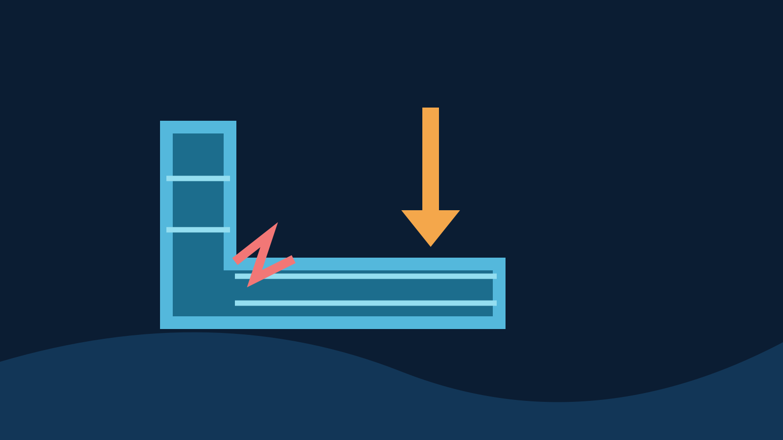
Load and geometry combine with the print process to determine where a part fails.
Start with the load
Ask where a force acts, in which direction and how often. Tension pulls a part apart; compression squeezes it; bending combines tension and compression; shear slides sections against one another; torsion twists; impact causes a short peak. Fatigue comes from repeated cycles, creep from a constant load over time. A hook, clip, shelf bracket and spacer therefore have different failure mechanisms.
| Load | What happens? | Example |
|---|---|---|
| Tension | The part is pulled apart. | Tie rod or loaded hook. |
| Compression | The part is squeezed. | Foot or spacer. |
| Bending | One side is in tension and the other in compression. | Shelf bracket, arm or clip. |
| Shear | Layers or sections try to slide past one another. | Pin, bolt hole or mounting lug. |
| Torsion | Twisting about the long axis. | Knob, coupling or shaft adapter. |
| Impact | A short, high load peak. | Bumper or protective cover. |
| Fatigue | Many repeated loading cycles. | Snap spring, hinge or vibrating bracket. |
| Creep | A constant load held for a long time. | Clamp kept under tension for months. |
Orientation and layer lines
FDM is anisotropic: an extrusion line within a layer is usually stronger than the bond between layers along Z. Temperature, contact area, cooling, flow and moisture affect that bond. Where possible, place critical tensile loads in the XY plane instead of pulling layers apart. One test cited in the source reports roughly 63 MPa for horizontal PLA specimens versus 31 MPa for vertical ones; that illustrates orientation, not a universal material value.
Within one layer, deposited lines are continuous. Between layers, new hot plastic must bond to material placed earlier. The source attributes those figures to a CNC Kitchen test. They are not a datasheet value for every PLA, but they illustrate the scale of the possible orientation effect.
Choose orientation for the real load path, not just the fewest supports. Printing at an angle, splitting a model or redesigning a joint may help. A 45-degree angle is no universal trick: it often adds support and creates other weak directions.
In a bracket, aim to keep major tensile stresses within layers. Printing at an angle may improve the weakest direction, but also make surfaces worse and add supports. If no single orientation works for a complex part, splitting it into better-oriented pieces with a purpose-designed joint can be stronger.
Design the load path
Sharp internal corners, abrupt thickness changes and holes close to an edge concentrate stress. Add fillets at loaded corners, triangular ribs at arms and brackets, enough material around bolt holes, and local thickness where needed. Match wall thickness to realistic line widths when useful. Split a complex part when its halves can then be printed in stronger orientations.
Practical design rules
- Add fillets to heavily loaded inside corners; even a small radius can reduce a local stress peak.
- Increase cross-section where the bending moment is high rather than making the whole part solid.
- Put triangular ribs or gussets between a base and wall or arm.
- Do not place bolt holes so close to an edge that only a few extrusion lines remain.
- Use wall thicknesses compatible with realistic line-width multiples when uniform walls and dimensions matter.
- Split a complex part if each half can then be printed in a better orientation.
For bending, material near the outside of a section is particularly effective. Increasing walls/perimeters is therefore often the first adjustment. Four to six walls with moderate infill can be a starting point for functional parts, but nozzle, size and load decide the actual setting. Infill supports top surfaces and connects walls; local modifiers beat 100% infill everywhere when only a bolt hole needs reinforcement. Gyroid and cubic support loads in several directions; rectilinear can be efficient for one dominant direction. Lightning mainly supports top surfaces with little material.
Outer walls form the skin and carry much of the stress in many load cases. The Prusa source therefore recommends increasing perimeters first for stronger parts. Infill is still useful: it supports top surfaces, connects walls, adds mass and can carry compression or shear. Its pattern changes internal force paths. Beyond a certain density, extra strength often grows much more slowly than print time and material use. If only a mounting point needs greater density, use a local modifier.
Process and layer bonding
Insufficient nozzle temperature, under-extrusion, speed beyond the maximum volumetric flow, too much cooling and wet filament can weaken layer bonding. Drafts or an unsuitable chamber increase warping and internal stress. Higher temperature is not always better: excessive heat harms detail and overhangs. Tune within the actual filament's suitable range.
| Factor | What goes wrong? | Likely effect |
|---|---|---|
| Nozzle temperature | Plastic does not fuse sufficiently. | Weak Z bond and matte or rough surfaces. |
| Flow | Under-extrusion or incorrect Flow Ratio. | Less contact between lines and layers. |
| Cooling | Too much for a technical plastic. | A layer cools before good bonding develops. |
| Speed/MVS | Hotend cannot melt the requested volume. | Under-extrusion at high flow. |
| Moisture | Water evaporates during extrusion. | Bubbles, inconsistent flow and surface defects. |
| Chamber/drafts | Large temperature gradient. | Warping and internal stress. |
A larger nozzle and wider lines can build thick walls faster at the cost of fine XY detail. Thinner layers are not automatically stronger: layer height changes interface count, bead geometry and thermal history. Top and bottom shells are structural skins in flat parts, not merely cosmetic settings.
A larger nozzle can create a thick wall with fewer perimeters and shorten functional-part print time, but small XY details become coarser. Thin layers mean more layer interfaces; thick layers change bead geometry. Select layer height from geometry, reliability, time and actual tests, not the rule that lower is always stronger. In a flat panel, one or two top and bottom layers behave very differently from a substantial skin that resists bending and local compression.
Material, joints and time
Stiffness, toughness and strength are different. PLA can be stiff; PETG or PA may absorb more impact. CF fill often improves stiffness and dimensional stability but may increase brittleness or reduce Z bonding. Select for heat, impact, creep, UV, wear, flexibility and chemicals. See the material selection guide.
A part often fails at its joint: allow enough edge distance and washers for bolts, design a robust boss for heat-set inserts, and do not rely only on infill around an arbitrary hole. Test repeated and sustained loading at operating temperature, not merely a single load.
Heat-set inserts distribute thread loading better than a small directly tapped hole. Installing one introduces heat, however; a thin boss may split. For heavily loaded attachments, edge distance, washers, local wall thickness and a designed load path matter more than extra infill around an arbitrary hole. A part that holds 20 kg once may crack after thousands of fatigue cycles or creep under that load over months, particularly at elevated temperatures.
Example: a wall bracket
- Find where the weight acts and estimate the bending moment.
- Connect base and arm with a triangular rib and a rounded inside corner.
- Orient the critical tensile side so it does not open along one layer boundary.
- Use enough walls, then add infill for internal support.
- Print a prototype, load it above normal use with an appropriate margin, and check for cracks, whitening, permanent deformation or layer separation.
Do not merely thicken the base and arm. The rib carries bending, the rounded inside corner reduces concentrated stress, and the orientation keeps the critical tensile side from opening a layer boundary. Inspect the prototype after loading for permanent deformation and early damage.
A practical starting recipe for strong prints
This is a way of thinking for workshop and hobby parts, not a certified profile:
- Orientation: place the largest tensile load in the XY plane where possible.
- Design: use fillets, ribs and enough local cross-section to resist stress peaks.
- Walls: increase perimeters before resorting to extremely high infill.
- Infill: match the pattern to the load and raise density locally where needed.
- Temperature and flow: achieve full, consistent extrusion within the material's limits.
- Cooling: enough for geometry, but not so much that layer bonding collapses.
- Filament: dry moisture-sensitive material.
- Test: measure and load a prototype; assumptions do not replace a material datasheet.
This is not a certified strength profile. Do not use an unvalidated hobby print as a safety-critical part for brakes, steering, lifting, pressure vessels, mains insulation or medical applications. For critical properties, consult the technical datasheet of the exact filament used.
Sources and further reading
Properties vary with manufacturer, colour, additives and test method. The source PDF cites the Prusa Knowledge Base on layers, perimeters and infill; a 2025 CNC Kitchen test of print orientation; an UltiMaker overview of shell thickness, infill and material choice; and the filament manufacturer's current TDS. This is decision support, not certification for safety-critical structures.