
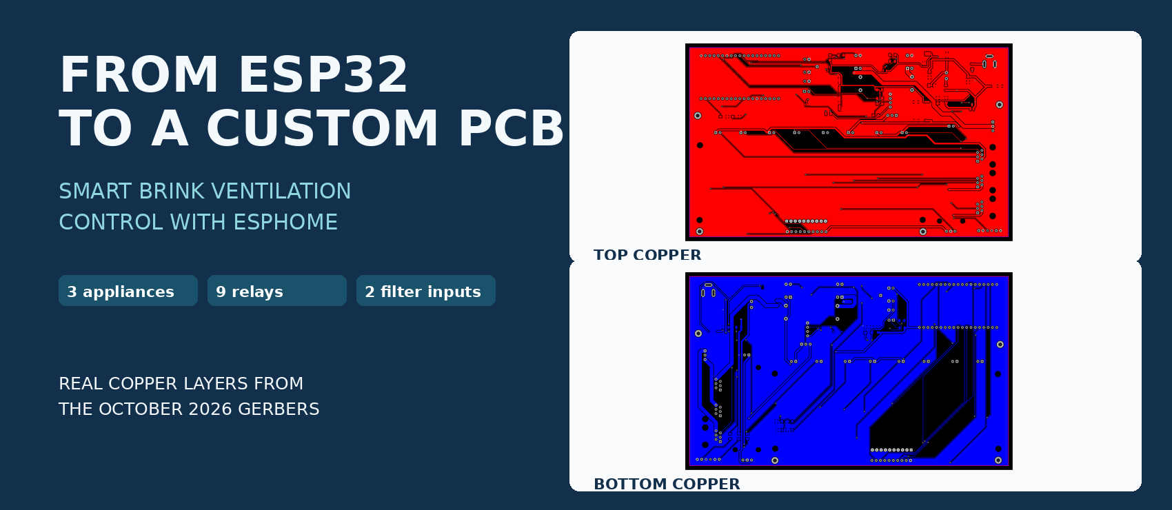
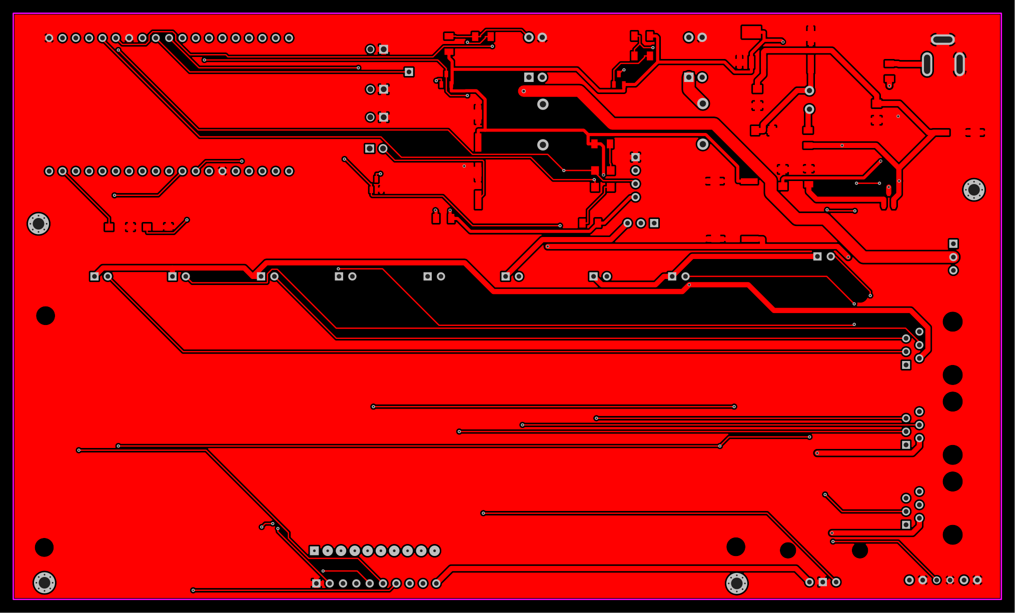
A standalone technical guide with ESPHome, relays, original PCB diagrams and safe measurement procedures. The project uses an ESP32, nine relay contacts, three control channels and filter monitoring.
Scope and status. This guide is based on the custom HRV-PCB design of 10 October 2026, supplied Brink installation instructions for the Renovent Excellent 300/400 and Elan E, the existing ESPHome configuration and official ESPHome documentation. Relay control already working in the project provides the practical basis. New PCB functions and voltage measurements remain design features or test points until validated on a fully assembled board. This is not a Brink-approved modification.
1. Why control it yourself?
Standard ventilation controls normally work well. A physical switch is simple, needs no Wi-Fi and does its intended job. What it lacks is a connection to other information in the home: bathroom humidity, CO₂, presence, a night schedule or a temporary need for increased ventilation.
An ESP32 and ESPHome add that connection without replacing the Brink’s internal controller. The ESP32 commands relays. Those relays close the same low-voltage contacts a mechanical speed selector would close. Brink remains responsible for its fans, temperature sensors, heating regulation and safety functions. The key is to imitate an existing control interface electrically, not to drive a fan directly with PWM or mains voltage. This makes the arrangement understandable and, in principle, reversible.
A custom board can neatly bring three channels, power, filter monitoring and status indication together. Anyone not wanting a PCB can implement the same switching principle with an ESP32 and separate relay modules, provided their electrical characteristics match.
2. Two units, three independent controls
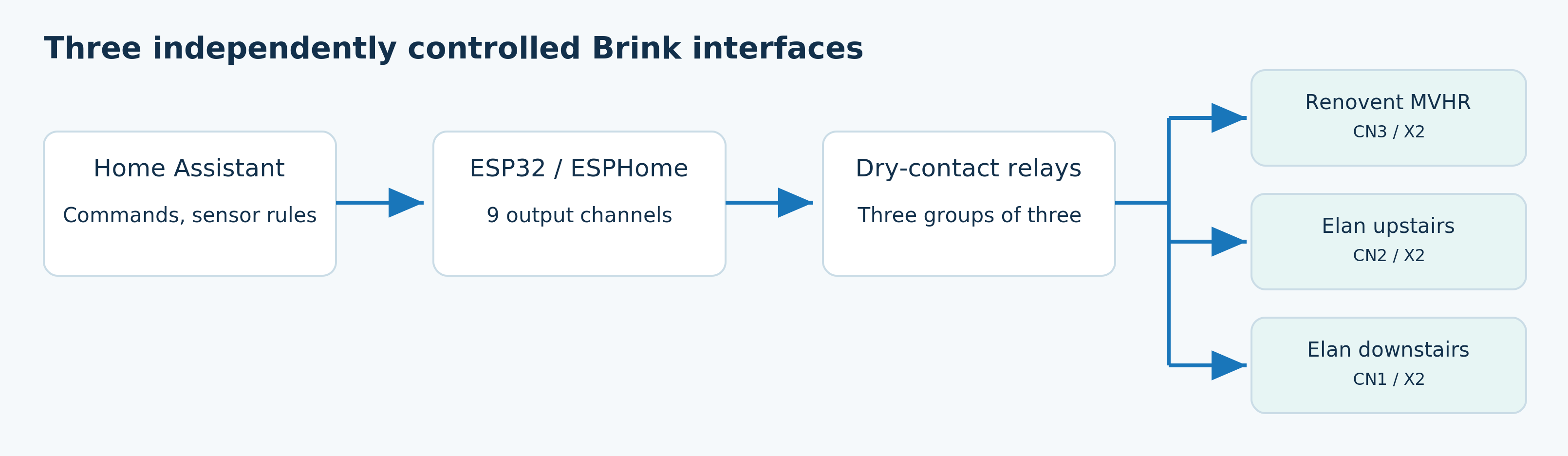
The Brink Renovent Excellent 300/400 is a balanced heat recovery ventilation unit. It extracts polluted indoor air, supplies fresh outdoor air and transfers much of the heat in its exchanger without deliberately mixing the two streams. The unit’s controller ultimately implements the configured airflow.
The Brink Elan E is an electric air heater. This installation has two control zones, each with its own controller and X2 connector. Elan is not just a second HRV unit: its airflow can also depend on discharge temperature and the selected ventilation programme. The thermostat determines heat demand; the speed-selector interface does not directly change the temperature setting.
| Channel | Unit/zone in this home | Own X2 connector | GPIO contacts |
|---|---|---|---|
| 1 | Renovent Excellent 300/400 | CN3: HRV | 26, 27, 19 |
| 2 | Upper Elan E | CN2: chosen upper zone | 32, 23, 22 |
| 3 | Lower Elan E | CN1: chosen lower zone | 33, 25, 14 |
“Upper” and “lower” are labels from this home. Verify which physical Elan zone serves which room; the unit manual calls them zones 1 and 2.
3. What does the original selector do?
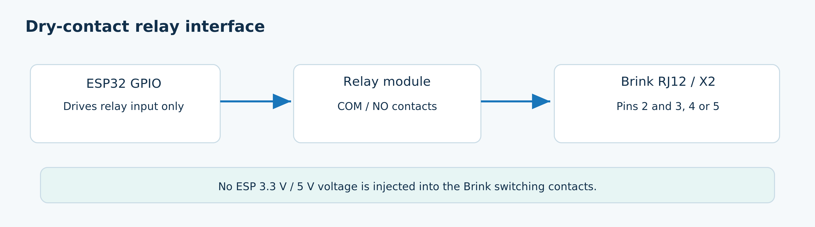
A conventional speed selector connects a shared wire to one of the ventilation unit’s control inputs, depending on its position. The unit detects the closed contact and applies its own control strategy.
A voltage-free contact does not deliver 5 V or 3.3 V from the ESP. It consists of two separate metal contacts that are joined on command. This differs from an actively driven voltage output. When the ESP energises a relay, COM and NO (normally open) close. To the Brink, that resembles a mechanical switch. The contact side and coil side must remain electrically separate on the actual relay module. A “10A/250VAC” marking rates the contact; it is not permission to put 230 V on Brink X2. X2 is only a low-voltage control interface.
4. RJ12/X2: six positions, no universal wire colours
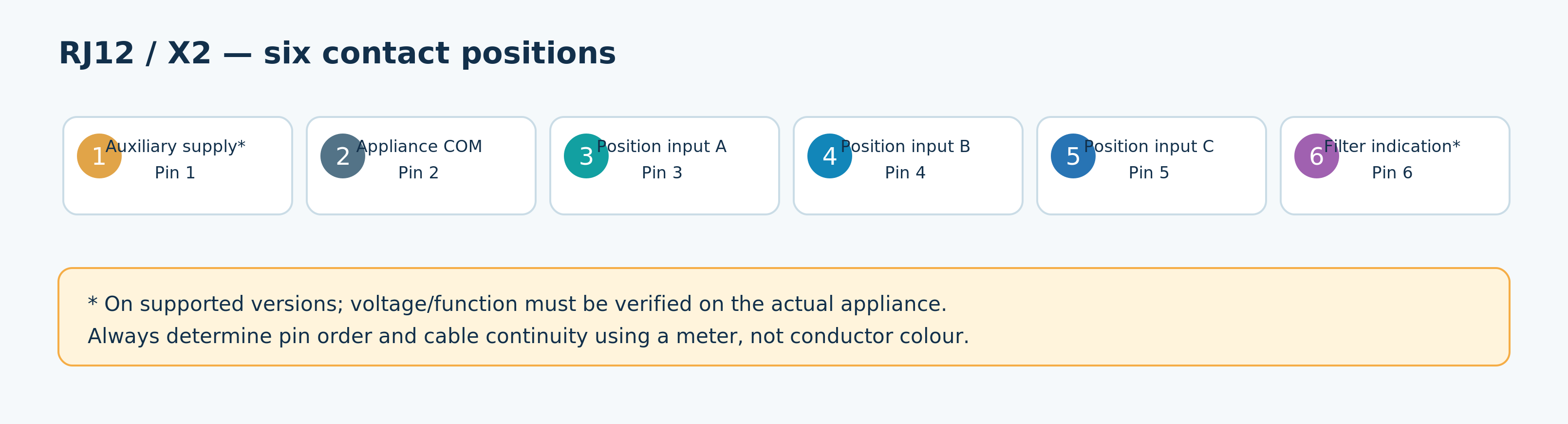
X2 versus X1 and X15
On the Renovent Excellent, X2 is for speed/setting control. Each Elan E zone has its own X2. X1 is another interface: eBus/OpenTherm depending on Renovent configuration, and eBus on Elan. X15 adds inputs on some Plus variants but is not interchangeable with RJ12-X2.
Brink distinguishes a four-core RJ11 arrangement for a three-position selector without filter indication from a six-core RJ12 arrangement for a four-position selector with filter indication. The manufacturer warns about wrongly assembled connectors; a reversed modular plug is a known cause when setting 2 does not work.
Pins in the custom PCB design
| X2 pin | Function in this project | PCB connection and limitation |
|---|---|---|
| 1 | Not connected on this PCB | May carry an internal auxiliary supply on a supported Renovent variant; do not connect to external 5 V or ESP power. |
| 2 | Common/return for the specific unit | HRV GND1, upper Elan GND2 or lower Elan GND3; not ESP-GND. |
| 3 | Selector contact A | Only through dry relay COM/NO to pin 2. |
| 4 | Selector contact B | Only through dry relay COM/NO to pin 2. |
| 5 | Selector contact C | Only through dry relay COM/NO to pin 2. |
| 6 | Filter indication | Via series resistor and optocoupler; measure voltage and polarity first, never straight to GPIO. |
This is the project pinout in the drawn schematic, not an assertion that every generation of every Brink product is identical. Compare the unit instructions and cable, and physically test the real connector. Wire colour is never a reliable indication of function; modular cables vary in order, mirroring and colour code.
Straight-through versus mirrored
With two RJ12 plugs, the wires may appear reversed as soon as you turn one plug over. That does not prove the electrical mapping right or wrong. Suppliers use different colour sequences and some cables are crossed. Physically identify all six contact positions at both ends, record the viewing direction and use a multimeter in continuity mode to establish which positions really connect. Only then finalise a wiring diagram. A plug illustration does not replace this test.
5. Switching one unit with three relays
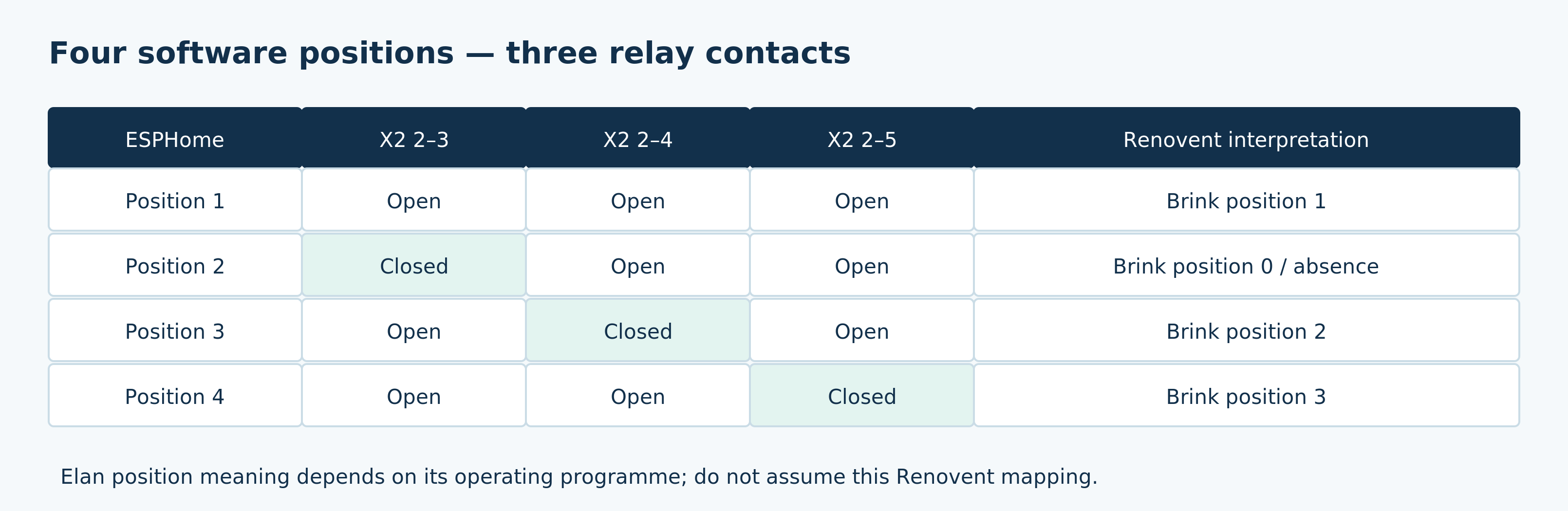
One unit needs three normally open contacts. Its own X2 pin 2 goes to COM on each of its three relays. The three NO terminals go separately to X2 pins 3, 4 and 5. NC is unused.
| ESPHome position | Pins 2–3 | Pins 2–4 | Pins 2–5 | Renovent Excellent in this installation |
|---|---|---|---|---|
| 1 | Open | Open | Open | Brink setting 1, normal rest |
| 2 | Closed | Open | Open | Brink setting 0, absence/minimum |
| 3 | Open | Closed | Open | Brink setting 2 |
| 4 | Open | Open | Closed | Brink setting 3 |
There are three relay positions plus one with every contact open. An ESPHome position names a contact combination; a Brink setting is what the unit does with it. Their numbers are not equivalent. The Renovent mapping follows the practical Excellent 300/400 pinout in this project. A real Elan zone follows its own programme; do not label its positions 0/1/2/3 or assign fixed airflow without separate verification. Record actual airflow only after testing the unit.
Why make all contacts open the baseline? The Renovent manual says the unit runs at setting 1 without a connected selector. In this project, “all relays off” is therefore a logical recovery state, not the lowest possible Brink setting or proof that minimum ventilation is sufficient. On Elan, the internal controller decides what the fan does.
Why not NC? NO contacts fall open when relay power disappears. An NC contact would close on power loss and could request an unwanted setting. NO provides a clear baseline for this design, but real failure behaviour still needs testing.
6. Nine GPIOs, three independent groups
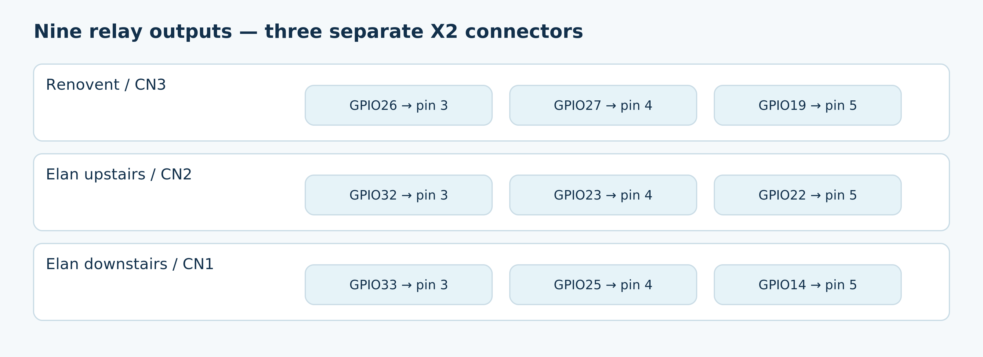
| Unit and PCB connector | Contact A: X2 pin 3 | Contact B: X2 pin 4 | Contact C: X2 pin 5 | Own common |
|---|---|---|---|---|
| Renovent HRV / CN3 | GPIO26 | GPIO27 | GPIO19 | GND1 |
| Upper Elan / CN2 | GPIO32 | GPIO23 | GPIO22 | GND2 |
| Lower Elan / CN1 | GPIO33 | GPIO25 | GPIO14 | GND3 |
The board uses a separate eight-channel relay module and an additional single-channel module. The electronics, supply and signal polarity of the modules actually fitted must match the firmware. Some relay modules are active-low and switch on when a GPIO goes LOW.
These GPIOs identify signal nets in the PCB design; they do not guarantee the mapping to the physically fitted module channels. Check J2 to IN1–IN8, J1 to the separate relay and the contacts through H1–H10 individually. A reversed ribbon cable can change the entire contact order while the YAML still looks right.
7. Interlocks matter but are not hardware protection
A rapid change from position 4 to position 2 could briefly activate both the third and first relays without appropriate logic. Firmware can open the old contacts first and then close the new one. ESPHome provides interlock and interlock_wait_time. The three HRV contacts block one another, but not the Elan contacts; each unit has a separate group.
ESPHome explicitly warns that software interlocks are not guaranteed hardware interlocks during a software bug or reset. restore_mode: ALWAYS_OFF initialises a GPIO switch off once firmware is running. It does not guarantee that an external active-low module never energises before initialisation. Test cold boot, reset, supply sag and welded contacts while disconnected from Brink.
8. Filter detection: roughly 24 V to a 3.3V logic signal
RJ12 filter indication is separate from selector contacts. The design expects roughly 24 V on the filter line during an alert. The precise electrical behaviour of both Elan X2 outputs has not been fully established as a datasheet value. Measure voltage, polarity and behaviour on the real installation before connecting electronics. An ESP32 GPIO is not 24V-tolerant.
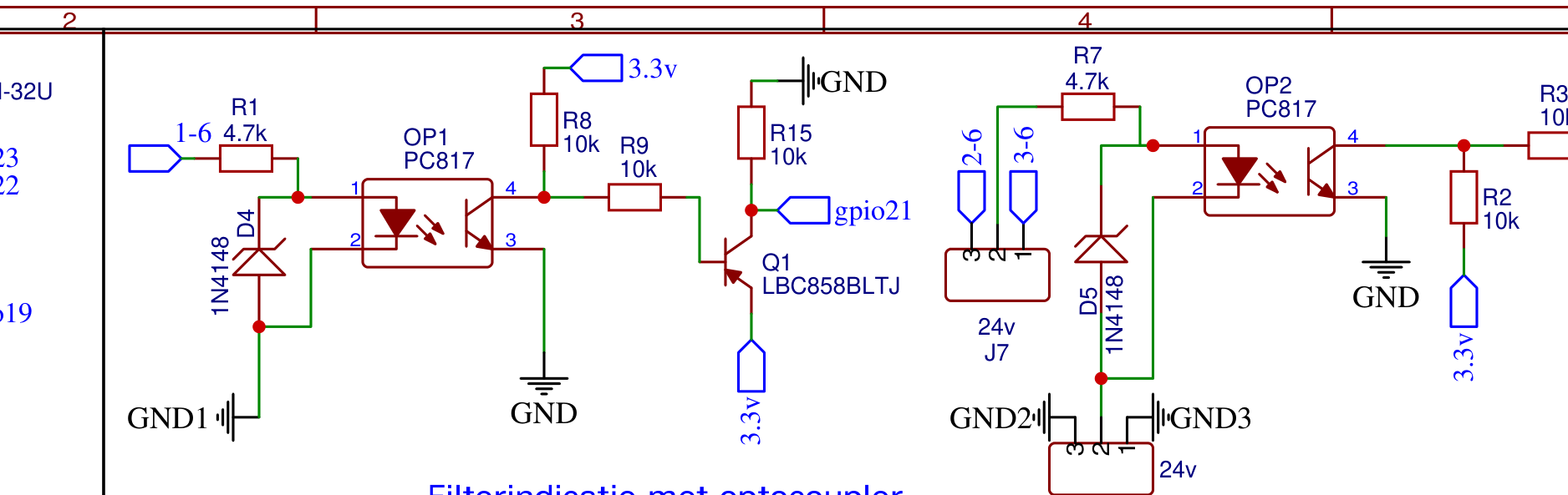
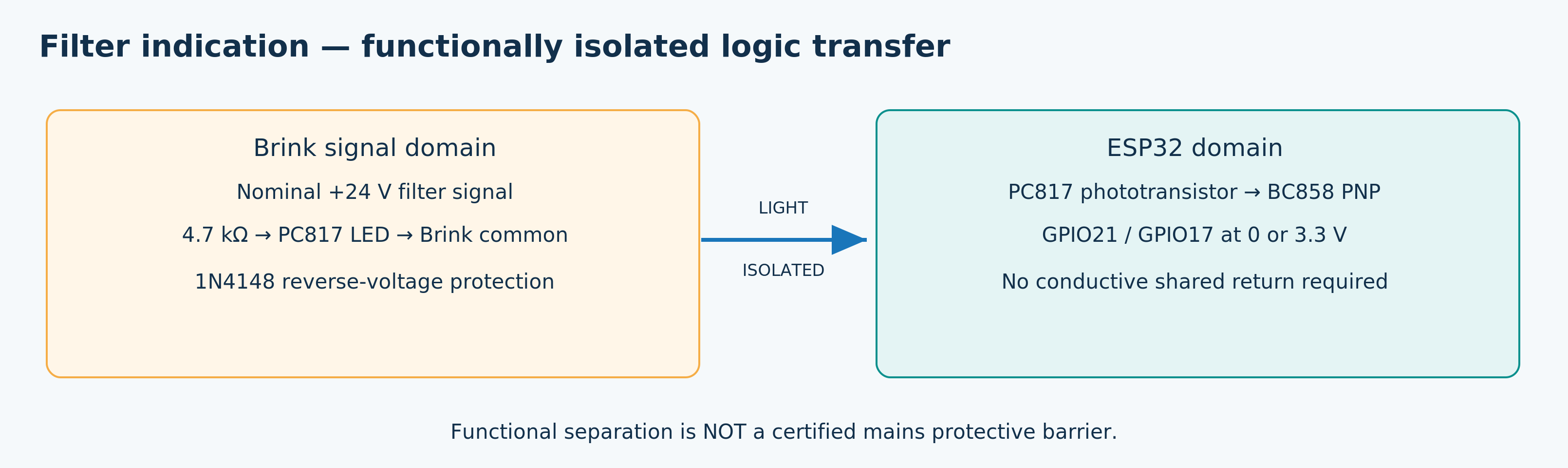
This PCB uses a PC817 optocoupler. An LED on the Brink side controls a transistor on the ESP side optically, so the Brink common need not be tied directly to ESP-GND. This is functional isolation, not a certified safety barrier or proven mains protective insulation; isolation rating, creepage, clearance and component selection remain design requirements.
Input: R1/R7 and D4/D5
The filter line goes through 4.7 kΩ to the PC817 LED; the return goes to the common of the same device. Assuming 24.0 V and roughly 1.2 V LED forward voltage gives I = (24.0 V − 1.2 V) / 4,700 Ω ≈ 4.85 mA. The resistor dissipates about 0.11 W; a suitable 0.25W part has nominal margin here. D4 and D5 are antiparallel 1N4148 diodes across the optocoupler LEDs to limit reverse voltage. Each diode’s cathode belongs on the series-resistor/opto-pin-1 side. The calculation does not establish that every Elan pin 6 actually provides 24 V.
Output: PC817, BC858 and GPIO
The PC817 phototransistor pulls collector pin 4 down to pin 3 on ESP-GND. A 10k pull-up holds the node HIGH at rest. A BC858 PNP stage with base resistor and GPIO pulldown gives the intended logic: no filter alert = GPIO LOW; filter alert = GPIO HIGH, around 3.3 V. The HRV uses GPIO21 and the selected Elan zone GPIO17. Because the hardware stage deliberately inverts the signal, ESPHome must not add inverted: true here. Measure the result on the final hardware.
9. Choosing the Elan filter source with J7 and J10
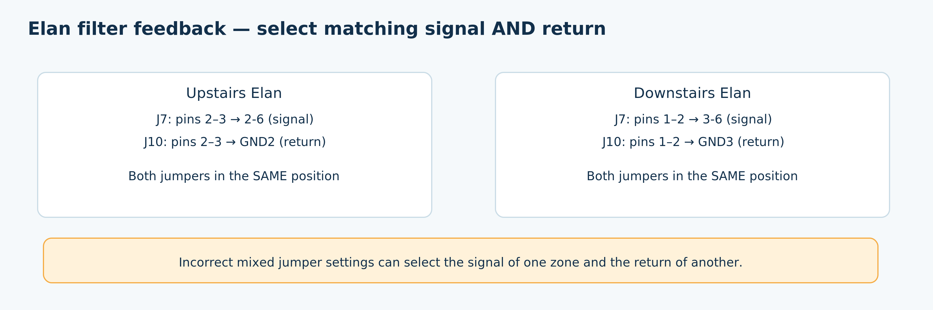
Both Elan E zones have their own X2. The design selects which zone’s filter indication is measured. J7 selects the pin-6 signal and J10 its matching pin-2 return. Both jumpers must choose the same zone: according to the current EasyEDA labels, 2–3 for upper and 1–2 for lower. Verify the real silkscreen and header orientation before assembly.
This prevents measuring pin 6 of one zone against the other’s common. Do not bridge GND2 and GND3 without verification. A linked two-pole selector could reduce the risk of mismatched jumper positions in a future revision.
10. ESP32, power and boot behaviour
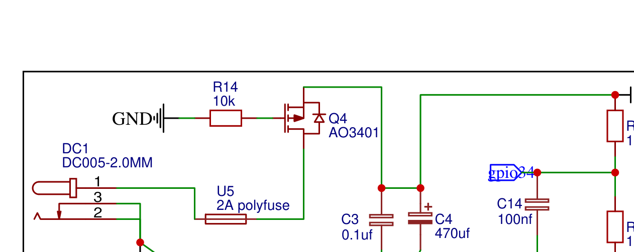
The project uses an ESP32 DevKitC and an external regulated 5V supply. The PCB has a 2A U5 polyfuse, AO3401 P-MOSFET Q4 for reverse-polarity protection and AMS1117-3.3 U7 for additional 3.3V circuitry. The DevKit receives 5 V through its designated header and uses its own regulator for its internal 3.3V rail. Check DC jack pins, MOSFET footprint and the 22µF AMS1117 output capacitor’s actual type/ESR and loaded stability.
R12 and R13, both 100 kΩ, halve VCC: at 5.00 V, GPIO34 sees approximately 2.50 V. A 100nF capacitor filters fast noise. After calibration, the ADC value helps with slow power monitoring, but it cannot reliably announce complete power failure because the ESP also shuts down.
The PCB has status, filter and fault LEDs, a buzzer, a flash/reset connection and a UART programming header. GPIO18 is reserved for future PWM; J8 is not a ready-made fan driver. GPIO5 drives the buzzer through Q3 and is a strapping pin: test cold boots on the final hardware. UART LEDs pulse active-low; the UART header uses 3.3V logic and must not be connected straight to a 5V adapter. Do not unknowingly power the DevKit through both USB and an external 5V header without understanding how that specific board isolates its sources. For data, a separate USB-UART adapter generally needs only TX, RX and GND; do not parallel power sources without suitable isolation.
11. ESPHome: from contacts to three controls
Firmware first defines nine GPIO switches, then groups them by unit with interlocks. A higher-level interface provides one select for each unit, so users see positions 1–4 rather than nine separate relays. The separate original example configuration uses the PCB’s GPIOs; replace Wi-Fi secrets and confirm the polarity of your own modules. The channel below carries the values shown in the source article; it does not replace complete firmware or prove hardware validation.
One channel in full
switch:
  - platform: gpio
    id: wtw_a
    name: "WTW contact A - pin 3"
    pin: GPIO26
    inverted: false
    restore_mode: ALWAYS_OFF
    interlock: [wtw_b, wtw_c]
    interlock_wait_time: 100ms
  - platform: gpio
    id: wtw_b
    name: "WTW contact B - pin 4"
    pin: GPIO27
    inverted: false
    restore_mode: ALWAYS_OFF
    interlock: [wtw_a, wtw_c]
    interlock_wait_time: 100ms
  - platform: gpio
    id: wtw_c
    name: "WTW contact C - pin 5"
    pin: GPIO19
    inverted: false
    restore_mode: ALWAYS_OFF
    interlock: [wtw_a, wtw_b]
    interlock_wait_time: 100ms
When all three are OFF, all NO contacts are open on a normal active-high relay setup. To choose a contact, ESPHome energises that relay while the interlock switches the other two off. 100ms is a configured software pause, not an automatically measured mechanical relay delay.
Four positions in Home Assistant
A template select can combine the contact choices. With optimistic: true, the displayed position is the requested state, not a measurement of closed relay contacts. A faulty relay or disconnected module is not automatically detected.
select:
  - platform: template
    name: "WTW ventilatiepositie"
    id: wtw_position
    optimistic: true
    restore_value: false
    initial_option: "Positie 1"
    options: ["Positie 1", "Positie 2", "Positie 3", "Positie 4"]
    set_action:
      - if:
          condition:
            lambda: 'return x == "Positie 1";'
          then:
            - switch.turn_off: wtw_a
            - switch.turn_off: wtw_b
            - switch.turn_off: wtw_c
      - if:
          condition:
            lambda: 'return x == "Positie 2";'
          then:
            - switch.turn_on: wtw_a
      - if:
          condition:
            lambda: 'return x == "Positie 3";'
          then:
            - switch.turn_on: wtw_b
      - if:
          condition:
            lambda: 'return x == "Positie 4";'
          then:
            - switch.turn_on: wtw_c
Both Elan groups work in the same way with their own GPIOs. Only rename positions “low”, “normal”, “high” or “boost” after verifying their actual functions on your unit.
Filter alerts and VCC
The design allows both filter channels to be read as digital inputs. The PNP inversion stage makes HIGH the alert state. The ADC on GPIO34 indicates VCC after a divide-by-two circuit; calibrate it against a multimeter on your ESP32 and apply ESPHome filters if needed.
binary_sensor:
  - platform: gpio
    pin: GPIO21
    name: "WTW filtermelding"
    device_class: problem
  - platform: gpio
    pin: GPIO17
    name: "Elan filtermelding (gekozen zone)"
    device_class: problem
sensor:
  - platform: adc
    pin: GPIO34
    name: "PCB VCC indicatie"
    attenuation: 12db
    update_interval: 30s
    filters:
      - multiply: 2.0
12. Automating with Home Assistant
Hardware determines which contact can be switched; Home Assistant decides when another setting makes sense.
- Bathroom: temporarily request a higher HRV position when relative humidity clearly rises above its normal trend. Add hysteresis and a minimum run time so a sensor fluctuating around a threshold does not continually switch relays.
- CO₂ control: temporarily increase ventilation when CO₂ remains elevated in an occupied room, provided the measurement is reliable enough and the chosen setting actually delivers suitable airflow.
- Night programme: consider a quieter baseline for reduced noise, without automating away legally and physically necessary ventilation. The system must continue supplying sufficient fresh air.
- Filter alerts: send a push notification when GPIO21 or GPIO17 becomes active, perhaps with a reminder until the filter has really been checked and the unit alert reset.
- Heating interaction: account for Elan programmes. A higher fan setting is not necessarily better for heating or comfort. Test its effect and do not override internal temperature or safety logic.
13. Safety: limits of the modification
This low-voltage control interface belongs to units containing internal 230V electronics. Five boundaries follow:
- Never inject external 5 V, 24 V or 230 V into X2 selector contacts. Relays only bridge intended contact pins. The filter line is separate and is neither a relay supply nor a direct GPIO input.
- Keep GND1 (HRV), GND2 (upper Elan), GND3 (lower Elan) and ESP-GND separate. Only the optocoupler’s transistor output uses ESP-GND. An unintended cable or ground-plane connection defeats the intended isolation.
- Define start-up and failure behaviour in advance. Firmware turns outputs off explicitly, but at reset not all ESP32 pins are immediately under its control. An active-low relay may briefly energise. Test while disconnected from the units.
- Do not modify internal mains components of the Renovent or Elan. Power down according to Brink instructions before checks; X2 is unsuitable for mains voltage.
- Schematics and Gerbers are not electrical certification. On the real assembly assess footprints, jack pinouts, trace width, spacing, power, housing, strain relief and relevant product requirements. Shield live parts in an appropriate construction.
At this revision the PCB has only been reviewed as a schematic/board design. An optocoupler offers functional isolation, not automatically proven mains protective insulation or product approval. In use, check actual airflow at chosen settings and avoid prolonged under-ventilation.
14. From test bench to connected system
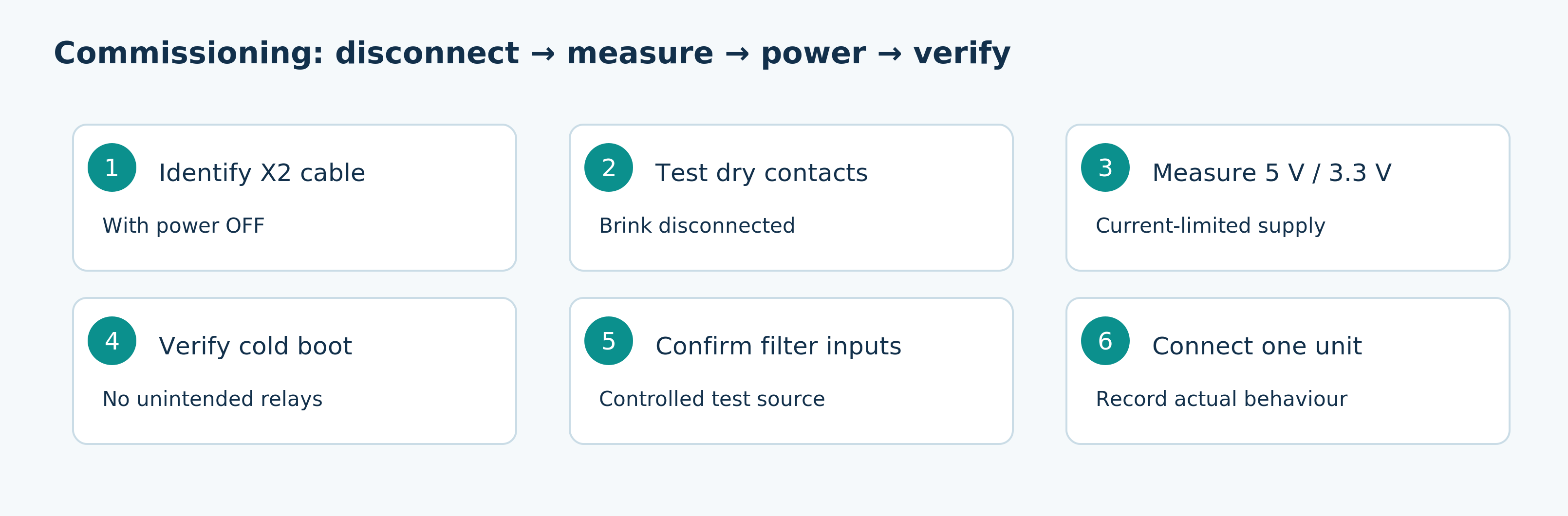
Commission in the sequence cable → power → function.
Step 1. Check cables and relays with power off
Make a table for X2 pins 1–6, mark the actual viewing side of the RJ12 plug and test continuity to the PCB connector pad. Check each relay’s NO and COM: open at rest, closed on manual activation. Leave the units disconnected. Confirm GND1/GND2/GND3 are not unintentionally joined to ESP-GND.
Step 2. Check power and start-up without Brink units
Connect the verified 5V adapter. Measure the PCB’s 5V and 3.3V rails and watch for abnormal AMS1117 heating. Switch GPIOs individually and verify with a multimeter which external relays actually close. Repeat after power-off, power-on, ESP reset and temporary Wi-Fi loss. No unintended extra contact combination should arise.
Step 3. Simulate or measure the filter circuit first
Before connecting, measure the possible filter output of the relevant Brink unit under a controlled plan and applicable electrical safety rules. A simulated 24V source must match the intended polarity, current limit and isolation. Check LOW without filter voltage and approximately 3.3V HIGH with it on GPIO21/17. Set J7 and J10 to the same Elan channel.
Step 4. Connect one unit at a time
Start with the HRV. Close one contact, check which setting the unit actually registers and record the airflow. Repeat for the other HRV contacts and then the three contacts on each Elan zone. Check that heating and protections continue to work normally.
Step 5. Automate and log
Enable automation only when manual positions are reproducible. Keep a test log with date, firmware version, relay make/model, measured voltages, jumper positions, requested position and observed unit response. This helps distinguish later problems from software changes.
15. Troubleshooting: common failures
| Symptom | Possible cause | Targeted check |
|---|---|---|
| Wrong reaction to a position | Mirrored RJ12 plug or swapped pins | Test cable pin by pin. |
| Relay energises when OFF | Active-low module or wrong inverted |
Measure input level and NO continuity. |
| Multiple settings together | Missing interlock or boot pulse | Test software and cold boot. |
| Filter alert always active | Reversed filter line or opto/stage fault | Measure pins 6–2 and GPIO21/17. |
| Elan filter alert fluctuates | J7/J10 choose different zones | Set both jumpers to the same zone. |
| ESP32 resets on relay click | 5V supply sags or wiring/module fault | Measure VCC while switching. |
| Unit does not seem to stop | Internal Brink setting or Elan programme | Check programme and actual airflow. |
| Buzzer chirps at boot | GPIO5 is a strapping pin or floating | Check cold boot, pulldown and module setup. |
| Works via USB but not on its own | Power or boot configuration | Check supply and EN/GPIO0. |
A temporary ESPHome test mode without Home Assistant automations helps test the three contact groups independently. A measurement table and log can often isolate a fault to one device, cable, GPIO or relay channel.
16. Other ways to control Brink
- Separate relays and ESP32: nearly the same switching circuit without a dedicated PCB. Affordable for experiments, but wiring quickly becomes hard to follow with several zones and filter inputs.
- Custom PCB with relay modules: the arrangement here. Complete modules switch the contacts while the PCB organises connectors, power, measurement circuits and wiring. It remains maintainable if module types and pinouts are documented.
- Transistors or MOSFETs instead of relays: not a drop-in replacement. A MOSFET is not a galvanically isolated voltage-free contact. Suitable solid-state control requires knowing the Brink input voltage, polarity, maximum current and failure behaviour.
- eBus, OpenTherm or other interfaces: some Brink units provide communications buses with different capabilities. These are different protocols and vary by unit and configuration. X2/RJ12 was chosen here because its principle is visible and directly measurable.
17. Parts and maintainability
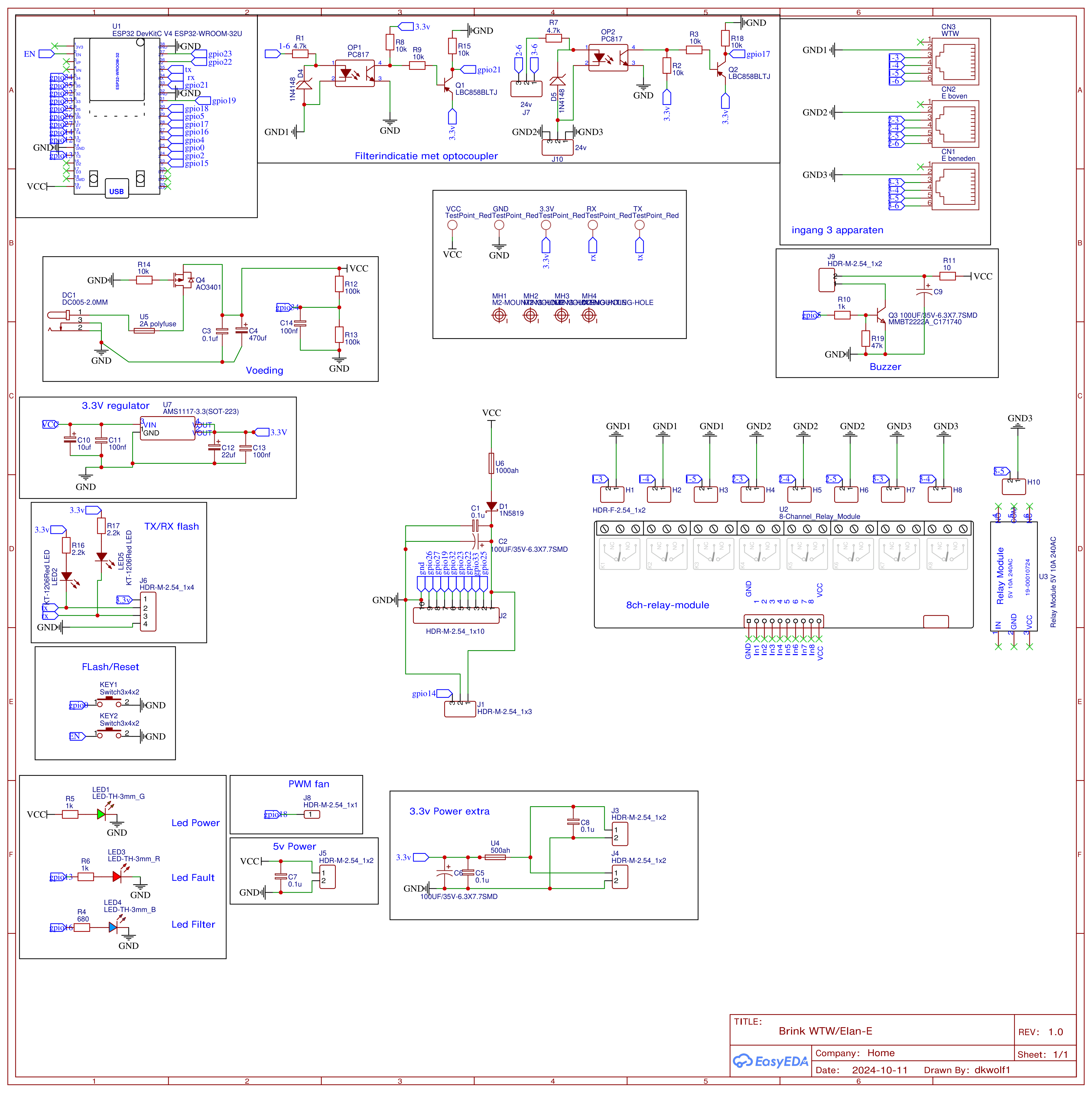
One channel minimally needs a controller with enough GPIOs, three suitable relay contacts, stable power, a correctly identified cable and an appropriate enclosure. The expanded project board adds headers, optocouplers, PNP transistors, protection diodes, status LEDs, a buzzer and a separate 3.3V regulator.
Cost depends on needed functions, the relay board and PCB batch size. No fixed price is printed: component prices, suppliers and shipping change, and the BOM must match the parts and footprints actually chosen.
Keep schematic, PCB revision, Gerber export, software version, relay-module details and pinout table together. Use clear net labels such as WTW_COM, ELAN_UP_COM and ELAN_DOWN_COM on the PCB; do not label every common merely GND. Document cables between the board and external module terminals too.
18. Conclusion and sources
Imitating a Brink speed selector with ESPHome contacts need not be electrically complicated. The key is not delivering another control voltage but closing the right voltage-free contacts. Three relays per unit yield four logical positions; three independent groups control Renovent, upper Elan and lower Elan separately.
The rules are clear: distinguish X2 from eBus/X15, measure the RJ12 cable, use the correct common for each channel, allow NO contacts to fall open on power loss and do not trust software interlocks blindly. Optocouplers can interface filter alerts if actual electrical characteristics have first been confirmed. The ESP32 switches, Brink controls its fans and Home Assistant adds context without replacing the manufacturer’s internal heating and safety controls.
- Brink, Renovent Excellent 300/400 (Plus) installation instructions, particularly §5.5.3, §10 and §11.1–11.2; supplied project copy and public copy from Brink Climate Systems.
- Brink, Elan E installation instructions Rev. C, especially §4.2, §10 and §11.1–11.2; supplied manual.
- Project source:
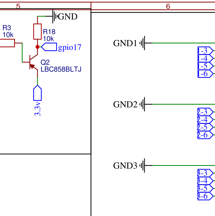
Schematic_WTW-pcb_2026-10-10.pdfand PCB/Gerber export of 10 October 2026 with CN1/CN2/CN3 and GPIO nets. The separate schematic export of 11 October is preserved as an image reference. - ESPHome documentation: GPIO Switch, Switch/restore mode and Template Select.
- Community discussion of RJ12 control: Let’s Control It forum, topic 5702; not used as the primary source for the pinout.
This technical article describes a private design, not an official Brink instruction, certificate or guarantee that a copy is safe in every installation. Anyone building or connecting it must assess parts, power, risks, measurements, compatibility and manufacturer instructions; work on internal mains components requires appropriate competence. Incorrect connections can damage electronics or disrupt ventilation and heating. A disclaimer does not automatically exclude legal liability. Offering or selling a product may trigger EU conformity, EMC, radio and product-safety duties; applicability depends on the product and its use. This article is not legal conformity advice.
Related reading: Brink Renovent with ESPHome, Renovent and Elan E through RJ12 and the Brink-PCB controller. Project code and documentation.