
A generic AC-side solution for grid-tied inverters that do not offer usable zero-export, export limiting or external shutdown control.
Dynamic energy tariffs can make solar export uneconomic or even costly during certain hours. The preferred solution is always a native inverter feature such as zero-export, active-power limiting or an official digital control input. But many inverters, microinverters and monitoring gateways simply do not expose that level of control.
A practical alternative is to go back to the electrical basics: interrupt the PV system’s AC grid connection with a correctly selected contactor. A Shelly Pro 1 can control the contactor coil. The Shelly therefore does not carry the PV current itself; it only commands the device that performs the power switching.
Important: this article explains the architecture, not a universal terminal-by-terminal wiring plan. Any modification to a 230/400 V distribution board must be designed and verified for the actual installation, manufacturer requirements and applicable electrical standards.
Why would you automatically disconnect PV?
In a traditional setup, solar generation first supplies the home and any surplus is exported. With dynamic tariffs, the value of that export can change every hour. When export remuneration becomes negative, every additional exported kWh may cost money.
An automatically switchable PV circuit can therefore be useful for negative-price curtailment. The same hardware can also provide remote manual shutdown, temporary production curtailment or integration with a broader energy-management system.
This approach is most relevant when the inverter does not provide native export control. If the manufacturer supports proper zero-export or active-power limiting, that is usually the better technical solution because it can modulate output instead of switching the complete system on and off.
The key principle: the Shelly is not the power switch
The installation consists of two separate electrical circuits:
- Power circuit: the AC connection of the PV inverter(s). The actual PV current flows here and is switched by a suitable contactor.
- Control circuit: a small protected 230 V circuit containing the Shelly and the contactor coil.
This separation is the main design principle. Although the Shelly Pro 1 has a relay output, the PV power itself does not need to pass through that relay. The Shelly energises A1/A2; the contactor handles the inverter current.
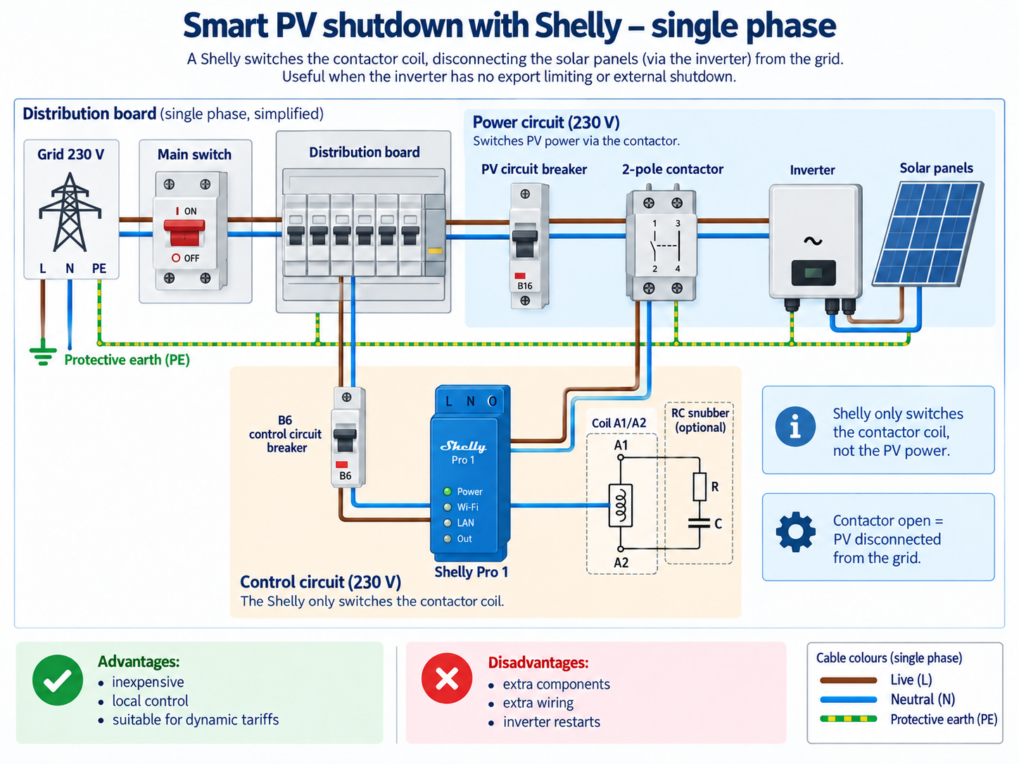
Figure 1 – Basic single-phase concept. The Shelly only controls the contactor coil. The contactor interrupts the inverter’s AC grid connection.
What hardware is required?
The final component selection depends on inverter power, existing protection, the earthing arrangement and manufacturer instructions. At a basic level you need:
- Shelly Pro 1 or a comparable DIN-rail controller with potential-free relay contacts.
- Contactor with the required number of poles, current rating and utilisation category for the PV AC circuit.
- Control-circuit protection, sized for the actual design.
- 230 V AC contactor coil if the control circuit is supplied directly from the distribution board.
- RC snubber or other suitable suppression across an AC coil where recommended.
- DIN-rail space, suitable enclosure, terminals and correctly sized conductors.
Existing PV protection and required isolation remain in place. Smart switching is not a substitute for mandatory PV protective devices or service isolation.
Single phase: what is actually switched?
For a conventional single-phase grid-tied inverter, the AC circuit consists of live and neutral. A design may use a 2-pole contactor to disconnect L and N together. Protective earth remains permanently connected.
Conceptually:
Grid / distribution board
        |
PV protection
        |
2-pole contactor  <--- Shelly controls coil only
        |
Inverter
        |
PV array

PE remains continuous.
The exact pole arrangement and isolation requirements depend on the installation and local regulations.
Three phase: the same idea with more poles
The architecture is identical for a three-phase inverter or multiple microinverters distributed over three phases. Only the power switching hardware changes.
A common arrangement uses a 4-pole contactor to switch L1, L2, L3 and N simultaneously. PE is never switched.
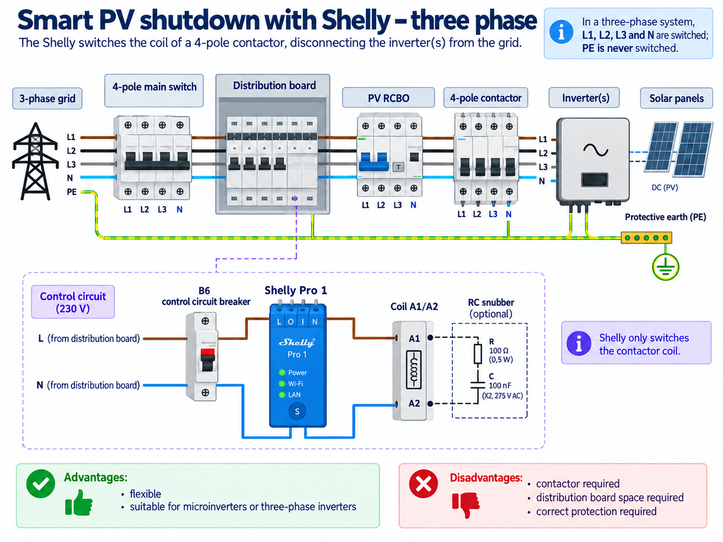
Figure 2 – Basic three-phase concept. L1, L2, L3 and N are switched by the contactor; protective earth remains permanently connected.
What happens to the inverter when the contactor opens?
A normal grid-tied inverter continuously monitors grid voltage and frequency. If the AC grid connection disappears, the inverter is expected to stop energising the grid circuit as part of its grid-monitoring and anti-islanding behaviour. Manufacturers such as SMA and Fronius explicitly document that their grid-connected inverters stop feed-in or disconnect from the utility grid during relevant grid faults or loss of grid conditions.
This does not mean the PV system is completely de-energised. A string inverter may still have DC voltage present on its PV inputs, and microinverter systems remain connected to the modules on the roof. AC curtailment is therefore not equivalent to full electrical isolation of the complete PV installation.
When the grid connection is restored, the inverter normally performs its grid checks again before resuming production. Reconnection time varies by inverter, grid code and manufacturer configuration.
NO or NC contactor?
This is an important design decision.
A normally open (NO) contactor is open when the coil is not energised. Loss of control power therefore tends to disconnect the PV system. This can be attractive when the desired failure state is PV OFF. The downside is that the coil may have to remain energised for most of the day when PV operation is normal.
A normally closed (NC) contactor keeps the PV circuit connected without coil power. The coil is only energised when curtailment is requested. That can be efficient for occasional negative-price shutdown, but a failure of the control circuit can leave the PV system operating.
There is no universal best choice. Price optimisation, availability and safety shutdown are different engineering objectives.
Why use an RC snubber?
A contactor coil is an inductive load. When the coil is switched off it can generate a short voltage transient. That transient can increase stress on relay contacts and generate electromagnetic interference.
A suitable RC snubber is placed in parallel with A1 and A2 on an AC coil. Shelly’s own documentation shows RC suppression for inductive loads, and Shelly also publishes an application example in which a Pro 1 controls a contactor.
What can the software do?
Once the electrical installation is inherently safe and correct, the software layer becomes useful.
The basic logic is simple:
if exporting is financially unfavourable:
    open contactor -> PV off
else:
    close contactor -> PV on
A real implementation should also include minimum ON/OFF times to prevent rapid cycling, state verification, alerts for unexpected states and defined behaviour after a reboot or network failure.
Home Assistant is a natural platform for this, but it is not mandatory. The Shelly Pro 1 supports local LAN or Wi-Fi control, an embedded web interface and scripting. Electrical protection, however, must never depend on Home Assistant, Wi-Fi or internet availability.
The big advantage: inverter-brand independence
This is the strongest feature of the approach. A contactor does not care about Modbus registers, cloud APIs, gateway firmware or the inverter brand. It simply interrupts the AC grid connection.
That makes the concept usable with many different grid-tied inverters and microinverters that lack a practical external power-control function.
The inverter must still behave correctly when the grid connection is removed, and the manufacturer must not prohibit the intended external AC switching method. Always check the manual for the exact inverter model.
Practical advantages and disadvantages
Advantages: broadly inverter-independent, local control is possible, uses standard DIN-rail hardware, the Shelly only handles coil current, works for both single- and three-phase systems, and integrates well with dynamic tariffs.
Disadvantages: ON/OFF control only, extra DIN space and wiring are required, the contactor and protection must be properly engineered, the inverter needs time to reconnect, and the failure mode of the control circuit must be deliberately designed.
When should you not use this approach?
Do not use it as a substitute for a superior native inverter function. If the manufacturer provides supported zero-export, active-power control, Modbus control or a digital curtailment input, that will often provide smoother and more efficient control.
It is also not automatically an emergency-stop system or a universal service isolator. Maintenance isolation, fire-safety functions and mandatory disconnection requirements are separate design topics.
Conclusion
A Shelly combined with a correctly selected contactor is a simple way to make a PV system remotely and automatically switchable when the inverter itself lacks suitable external control.
The principle is straightforward: the contactor switches the PV power circuit; the Shelly only switches the contactor coil. This keeps the smart electronics out of the high-current path and makes the concept compatible with a wide range of inverter brands.
It is not a replacement for true zero-export and it is not a universal wiring diagram. But for controlled AC curtailment during unfavourable export prices, it is a practical and highly automatable architecture.
Sources and further reading
- Shelly Pro 1 – official product information and specifications: https://www.shelly.com/products/shelly-pro-1
- Shelly Pro 1 – documentation including inductive-load / RC-snubber diagram: https://www.shelly.com/blogs/documentation/shelly-pro-1-v1
- Shelly – Pro 1 with a contactor for load shedding: https://www.shelly.com/blogs/documentation/using-shelly-pro-1-and-a-contactor-for-load-sheddi
- SMA – examples of grid monitoring and feed-in interruption during grid faults: https://manuals.sma.de/STPTL-30/en-US/391460235.html
- Fronius – documentation on anti-islanding and interruption of feed-in during grid failure: https://www.fronius.com/~/downloads/Solar%20Energy/Operating%20Instructions/42%2C0410%2C2028.pdf
- NEN 1010 – Dutch low-voltage installation standard: https://www.nen.nl/